
Business case for an offshore construction vessel with a shore power battery
A 75 MWh battery system costing $9.5M can save an offshore vessel ~ $900,000 in 10 years
Shore power for containerships is mandatory from 2030 onwards as per FuelEU. The creation of shore power infrastructure remains difficult and takes a long time however. Mobile shore power solutions, with- or without a battery will ensure port authorities compliance to regulations.
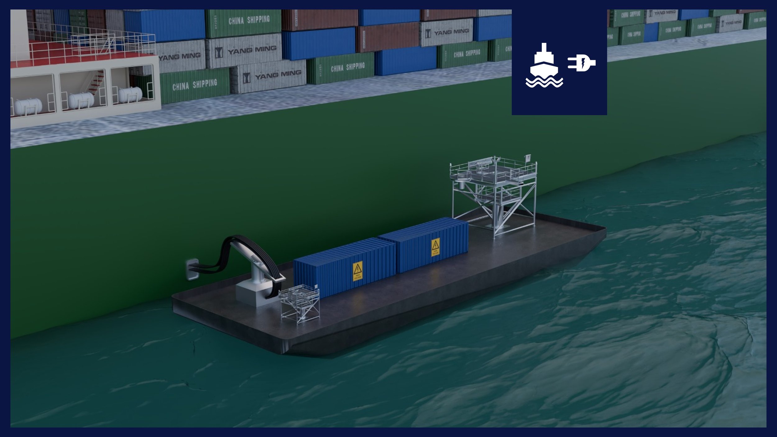
This analysis outlines a floating battery energy storage platform - referred to as the power barge - capable of delivering high-capacity shore power to offshore construction vessels. The system includes containerized batteries with a capacity of 75 MWh, a central DC backbone, DC/AC inverter, and high-voltage shore connection infrastructure (HVSC) rated at 5.644 kW. Performance and cost outcomes are calculated using a range of adjustable parameters including operating days, power prices, and energy policy incentives, particularly EU ETS.
The annual costs savings for the ship with an electricity price of $0.30 per kWh and 40 shore power days per year are in the order of $111,555 per year over the course of ten year. More than 85% of all cost reductions are due to reduced compliance cost: it is estimated more than $2M can be saved with EU ETS in the first 10 years. Conservative estimates for maintenance and EU ETS pricing are considered, which when altered could result in a more positive case. CAPEX costs for the ship are assumed to be zero. CAPEX costs for the power barge are estimated at $9.5M, with an estimated revenue of $2.5M per year based on a combination of income from shore power and grid services (FCR).
Use the tool below to customize a case study for yourself.


Pre-FEED Study
This pre-FEED (Front-End Engineering Design) study provides a technical and economic assessment of a floating battery-based shore power solution, focusing on layout, equipment, performance, and cost assumptions. It outlines the concept’s feasibility, key regulatory drivers, and baseline business case inputs for both the power barge and vessel operations. The full pre-FEED study, including detailed calculations, assumptions, and technical architecture, is available for download by registered members only. Become a member to access the complete document.
Members only
Ship - Technical
The offshore construction vessel used in the pre-FEED study (the ‘Windfarmer’) is designed for heavy-duty operations such as the installation of wind turbines and monopiles. When idling, it features a diesel-electric power system capable of meeting an average auxiliary load of 2.4 megawatts, with peak demands reaching up to 5 megawatts during crane or dynamic positioning operations. A total of 8 engines are installed with 6,000 kW power each. When idling, it is assumed that 2 engines are running at 20% load.
The vessel is considered to be ‘shore power ready’, already equipped with a high-voltage connection that meets IEC/IEEE 80005 standards. A parasitic load of 5 % is taken into account to reflect baseline energy use from onboard systems even when the ship is idle. For the purpose of this study, the analysis assumes the vessel is moored at the quayside 40 days per year. This means that multiple vessels are expected to make use of the infrastructure to meet the barge’s annual operational target. The technical configuration enables significant reductions in fuel consumption, emissions, and maintenance, supporting compliance with tightening EU and IMO decarbonization requirements.
Ship - Economical
In this case study, the shore power system is evaluated under the assumption that it must financially justify itself through a combination of fuel savings, reduced engine maintenance, and lower emissions, which result in lower compliance costs. While this framing supports a clear cost-benefit analysis, it is important to note that it does not reflect the full regulatory context and currently existing uncertainties. In the case shore power becomes mandatory for offshore vessels under FuelEU Maritime (which is unlikely), adoption will ultimately be a requirement rather than a financial choice.
For the purposes of this analysis, capital expenditure (CAPEX) related to ship-side retrofitting has been excluded, under the assumption that the vessel is already shore power ready. The focus is instead placed on operational expenditure (OPEX), with cost savings primarily coming from reduced EU ETS obligations, which account for a significant portion - 80% or more - of conventional operating costs. Other factors such as reduced maintenance costs contribute to the business case, while potential savings related to FuelEU Maritime and the IMO’s net-zero framework are acknowledged but excluded from the current calculation.
-
CAPEX costs are excluded from this study as it is assumed that the vessel is ‘Shore Power Ready’. -
For offshore construction vessels such as the Windfarmer, electricity and fuel-related costs dominate the operational expenditure (OPEX) profile during idle periods. In the 2028 baseline scenario, the total annual OPEX is estimated at approximately $48.5 million when using conventional auxiliary engines, compared to $48.4 million when connected to shore power. The difference represents a marginal reduction of ~$41,000 per year, or 0.1%, mostly driven by a reduction in compliance costs at the provided kWh rates.Under conventional operation, fuel and electricity costs account for over 66%, while EU ETS costs represent approximately 31% of the total OPEX. When switching to shore power, the fuel cost is replaced by purchased electricity at €0.30 per kWh, resulting in a slight increase in direct energy costs. However, this is partially offset by savings in engine maintenance and consumables (combined 5% reduction), as well as a 2% overall drop per year in EU ETS costs due to lower emissions.
The analysis assumes 100 shore power days per year, a parasitic engine load of 5%, and no additional financing or retrofit costs, as the vessel is considered shore-power ready. These assumptions result in stable OPEX with improved emissions compliance and a more favourable long-term outlook under rising carbon pricing.
Power Barge - Technical
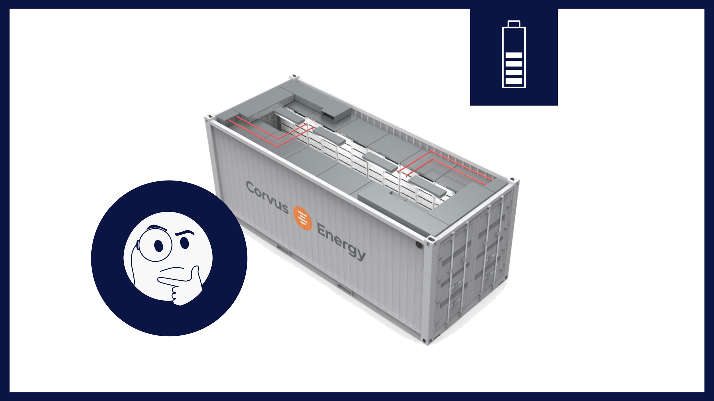
The power barge at the heart of this study is a floating battery energy storage system designed to deliver clean, high-capacity shore power to offshore construction vessels while at berth or on standby. It measures approximately 52.6 meters in length and 18.7 meters in width, and houses twelve containerized battery units based on lithium iron phosphate (LFP) chemistry. These units provide a total installed capacity of 75 MWh, of which 67.5 MWh is usable under a 90% depth-of-discharge assumption.
The onboard systems operate at a standard 1,040 volts DC, with power collected via a centralized DC busbar. This energy is then converted to 11 kV, 60 Hz AC using a high-capacity inverter system and delivered to the vessel through a high-voltage shore connection compliant with IEC/IEEE 80005 standards. The barge is charged via a Megawatt Charging System (MCS), capable of handling up to 4.5 MW using liquid-cooled cables.
All major components, including the fire suppression system, cooling, cable trays, and connection panels, are marine-rated and configured for modularity, safe access, and redundancy. This self-contained layout allows the barge to function as a mobile energy hub, supporting emissions reductions and regulatory compliance without the need for permanent grid infrastructure at the quay.
-
A key component of the power barge system is the barge itself, which must accommodate all major equipment, including twelve or more containerized battery units, DC busbars, inverters, and cable management systems—while still allowing for redundancy and ease of access for maintenance personnel. To support this, a medium-sized barge suitable for harbor-side or offshore floating operations is proposed. A general arrangement of the barge is shown to the right.The proposed barge measures approximately 52.6 meters in length, 18.7 meters in width, and 3.2 meters in depth. The layout features twelve evenly spaced battery containers organized in two rows of six, providing adequate clearance for ventilation, fire safety zoning, and maintenance access. Each container has an estimated weight of 28.5 metric tons, contributing to a total battery payload of approximately 342 metric tons.
Incoming power is assumed to be in DC, compatible with the Megawatt Charging System (MCS), which is located at the aft/starboard corner of the barge. This interface enables direct charging of the battery system from grid or renewable sources and can be operated without the need for cranes or special handling equipment. Outgoing power is assumed to be in AC, in line with IEC/IEEE 80005 requirements for high-voltage shore connection (HVSC) systems, and is located at the bow/port side.
Power from the battery system is collected via a DC busbar, inverted to AC, and distributed through a dedicated cable management system. The barge is equipped with accessible walkways, railings, and separated containers to ensure safe, modular, and flexible operation—well-suited for ship-to-shore power supply, grid resilience, or emission-free offshore construction support.
-
The incoming interface of the power barge is based on the Megawatt Charging System (MCS), located on the aft/starboard side. This interface connects the barge to external power sources—such as the onshore grid, hybrid generators, or renewable systems—for charging the onboard battery containers.The MCS is a standardized high-power DC connection system designed to support charging rates of up to 3.75 MW under standard conditions, with a maximum rated voltage of 1,250 V DC and currents up to 3,000 A. In applications where higher power transfer is needed, the system can be configured to deliver up to 4.5 MW, provided that liquid-cooled charging cables and connectors are used to manage thermal loads.
The system is designed for safe manual handling without cranes and features built-in communication and interlock mechanisms for secure operation. The interface aligns with evolving international standards such as ISO 15118-20 for communication and IEC 61851-23/-1 for DC charging systems, making it suitable for repeated use at designated high-power port charging locations.
-
The core of the energy storage system on board the power barge consists of twelve containerized lithium-ion battery units based on the CATL EnerX 0.5P platform. Each container is a self-contained, high-density energy storage solution integrating lithium iron phosphate (LFP) cells, battery management systems (BMS), thermal management, and fire suppression systems. Housed in standard 20-foot ISO transport frames, each container measures approximately 6.1 m × 2.44 m × 2.9 m and weighs 28.5 metric tons when fully assembled. Internally, each container contains four racks with eight battery packs per rack, yielding a total energy capacity of 6.25 MWh, of which 5.625 MWh is usable, assuming a 90% depth of discharge (DoD).The integrated BMS follows a three-level control architecture (Cell Supervision Circuit → Slave BMS → Master BMS), enabling continuous monitoring of voltage, current, and temperature across all cells. This ensures safe operation, cell balancing, and real-time diagnostics, with external communication via CAN and Modbus TCP protocols. Thermal regulation is maintained using a dedicated liquid cooling system, featuring a centralized chiller and integrated coolant distribution, enabling reliable operation across ambient temperatures from -20°C to +55°C. The system also includes a multi-tiered Fire Suppression System (FSS) with smoke, heat, hydrogen, and CO sensors, aerosol fire suppression, and dry pipe sprinklers—all powered by a dedicated 24-hour UPS backup.
Each battery container connects to a high-voltage DC interface, delivering power to the barge-wide busbar. The design meets international standards including IEC 62619, UL 9540A, and NFPA 855, and is optimized for modular integration with PCS, EMS, and vessel charging operations in offshore or harbor-based environments.
-
The DC output from two parallel-connected CATL EnerX battery strings - each consisting of six containers - feeds into a DC busbar rated for 1,000 V and 5,600 A. This busbar functions as the central power collection backbone of the power barge, interconnecting the outputs of all twelve containerized battery units and routing their combined energy to the inverter system.Arranged in a dual-side configuration, the busbar collects DC power from six containers on the port side and six on the starboard side. Each group of containers is connected in parallel, and their outputs are commingled through the busbar into a unified high-voltage DC output. This configuration enables a consolidated and balanced flow of energy to the downstream inverter stage, supporting continuous and reliable power delivery to connected vessels or onshore systems.
The DC busbar is designed to operate at nominal voltages between 750 V and 1,250 V DC, in line with the output voltage range of the CATL EnerX container systems. It is engineered to handle currents in the multi-kiloamp range, and in this configuration is capable of transmitting approximately 5.66 MW of power – twice that of a single battery container to accommodate the ship’s power demands
To ensure safety and performance, the busbar system incorporates features such as overcurrent protection, DC isolation, and interface points for voltage and temperature monitoring. It is housed in a protected cable management corridor, with symmetrical routing from both sides of the barge, minimizing impedance and ensuring efficient power aggregation.
The use of a centralized DC busbar simplifies system integration by reducing the number of inverter inputs required and allows for modular container replacement or maintenance without disrupting the entire power chain. Its layout is optimized for weight distribution and thermal management within the barge, and it forms a critical link between the battery system and the DC/AC conversion stage, enabling scalable, high-capacity energy delivery.
-
The DC/AC inverter system on the power barge serves as the interface between the DC power collected from the onboard battery containers and the high-voltage AC output delivered to the connected vessel. Located forward on the barge near the outgoing shore connection, the inverter system is designed to handle a nominal continuous power output of 2.4 MW, with the capability to ramp up to a maximum of 5.644 MW during peak load conditions.The inverter converts DC battery power to AC for standard ship power supply. The full system output is converted into an 11 kV, 3-phase, 60 Hz AC output suitable for high-voltage shore connection (HVSC) systems, resulting in an approximate output current of 329 A at a power factor of 0.9 under maximum load. The inverter system includes a power conversion unit (PCU), transformer, and associated protection and synchronization modules, forming a complete power conversion and export package. It features dynamic power ramping capabilities - up to 1 MW/s -to respond to variable load demands from the vessel. Advanced control systems manage real-time voltage and frequency regulation, and the inverter can operate in both grid-forming and grid-following modes depending on the vessel interface.
The inverter is to be housed in a weather-protected, ventilated enclosure on the barge deck, and should also include provisions for forced air or liquid cooling depending on the final equipment selection. It is connected to the outgoing high-voltage AC shore cable through an integrated cable management system and includes safety interlocks, isolation, and earthing in line with port state, classification society, and international standards.
The system is designed for compliance with IEC/IEEE 80005-1 and IEC 61850, enabling reliable and safe delivery of vessel-compatible AC power across a wide range of offshore and service ship types. For future flexibility, an optional DC bypass will be made available, allowing direct DC transfer to another vessel’s battery system via the Megawatt Charging System (MCS) without requiring conversion to AC.
-
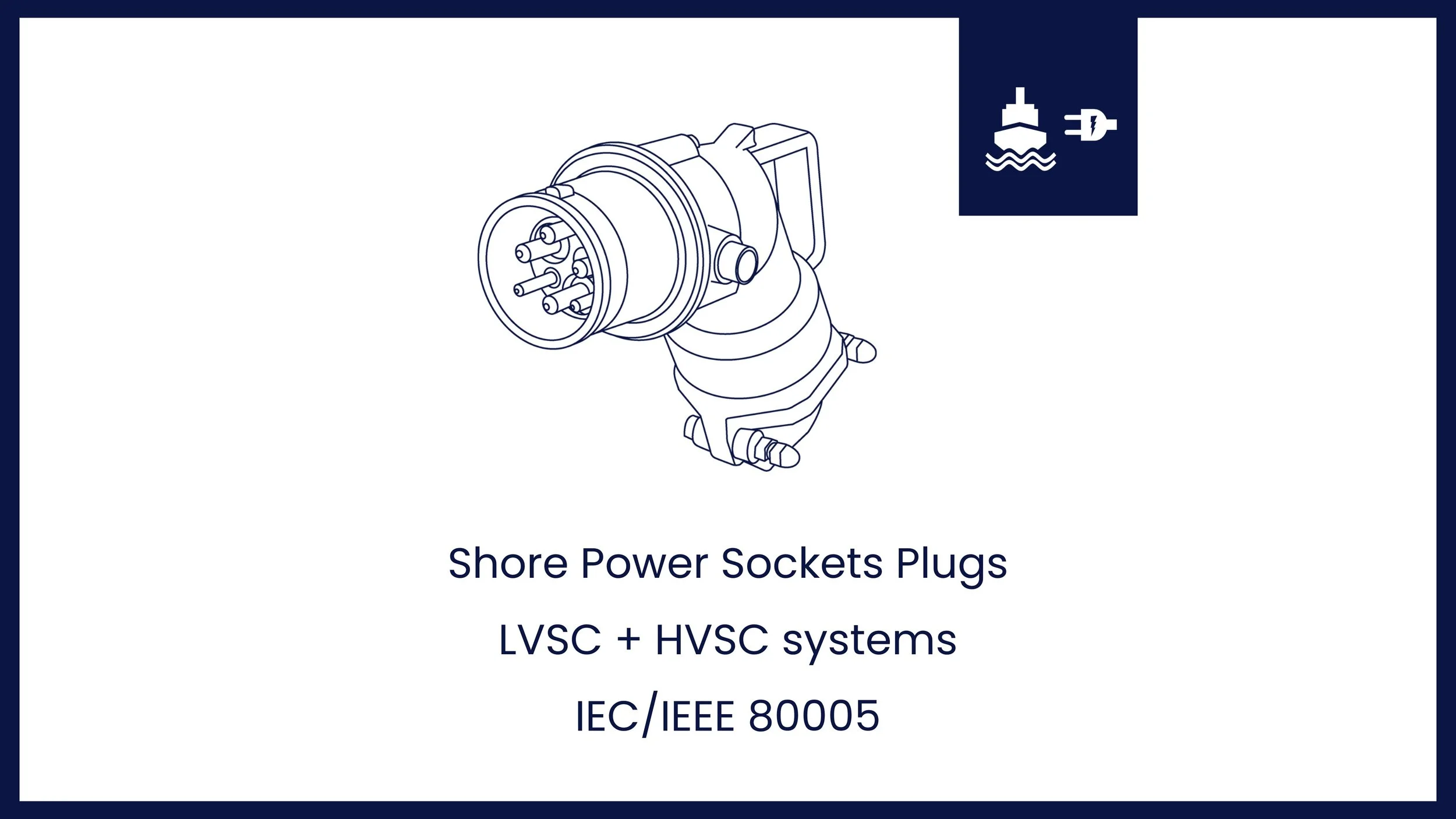
The final interface where AC power is supplied to the vessel is called the outgoing Cable Management System (CMS). It is the physical cable connecting the barge and the ship. It is a crucial aspect of design, described in detail in IEC/IEEE 80005-1 and 3, section 7.2 for cable management systems, and 7.3 for plugs and sockets, as well as IEC 62613-1 and 2.For an offshore construction vessel, a reel-type cable management system is preferred as the offshore ship will always have a crane on board that can reel the plug in to the right location. IEC/IEEE 80005 does not prescribed the plug types for HVSC offshore ship types, consequently it is assumed that the high-voltage plug and socket interface shall comply with IEC 62613-2 Type B, rated for 11 kV and 600 A.
According to Annexes in IEC 62613-2, especially configurations like Annex J (for complex vessels), a typical HVSC connector includes 3 power contacts: L1, L2, L3 (for 3-phase power) and 1 Earth Contact (E) for grounding and protection, as well as up to 7 pilot contacts, depending on the complexity of the vessel and its configuration, used for control, interlocks, synchronization, and communication. Type B setups typically support at least 2 pilot contacts (min), but higher-spec designs (like Annex J) go up to 7. Functions can include:
Pilot A: Earth continuity monitoring
Pilot B: Connector position verification
Pilot C: Voltage presence feedback
Pilot D-G: Optional for advanced comms or redundancy
-
The DC cabling system on board the power barge distributes power from the Megawatt Charging System (MCS) junction box to the twelve battery containers, and from there to the centralized DC busbar using a backbone cable architecture. The configuration consists of four parallel aluminium cables per polarity (positive and negative), running along the barge deck in dedicated cable trays. These backbone conductors form the main power distribution path, and each battery container is connected via a local junction box equipped with a DC-rated breaker or fuse for protection and isolation.
The system operates at a nominal voltage of 1,000 V DC, with a maximum system voltage of 1,250 V, and is designed to support 2.4 MW of continuous power and up to 5.644 MW during peak demand periods of up to 10 minutes. The selected 1,000 mm² aluminium XLPE-insulated power cables provide a continuous ampacity of approximately 900 A per conductor. In a four-cable-per-polarity configuration, this delivers a combined capacity of 3,600 A, comfortably covering the continuous load. The cables also have sufficient thermal headroom to handle short-term peak currents of ~5,600 A, with each conductor temporarily carrying up to 1,400 A.
Cables are routed in symmetrical trays along both sides of the deck, with T-tap junction boxes allowing each container to connect into the shared positive and negative rails. The system maintains balanced loading, controlled voltage drop, and clean integration with the overall energy management system. The total estimated cable length for this configuration, including backbone runs, branch leads, and slack, is approximately 600 to 700 meters. The design complies with applicable standards, including IEC 60287, IEC 60502-1, and IEC 60332-3, and supports maintainability, modularity, and safe operation under both steady and dynamic loading conditions.
Power Barge - Economical
The economic analysis of the power barge focuses on the costs and potential revenues associated with deploying and operating a floating battery energy storage system for shore power delivery. The study assumes the barge operates for 240 days per year, supplying power to vessels for 100 of those days based on a demand profile of 40 shore power days per vessel. That means at least 2.5 vessels need to be serviced each year.
Electricity is procured at a rate of $0.10 per kilowatt-hour and sold to vessels at $0.30 per kWh in the base case, with no green energy incentives included. Capital investment is assumed to be fully paid upfront, with financing optional, and the system is not subsidized in the default scenario. The analysis includes both capital expenditure (CAPEX) and operational expenditure (OPEX), and allows for the exploration of revenue streams such as grid services or rental revenues, depending on the operational profile selected.
-
The total capital expenditure for the power barge is estimated at $9.58 million, based on a breakdown of key components and services. This includes the barge structure itself, containerized battery units priced at $100 per kWh, high-voltage inverter systems, cable management interfaces, onboard cabling and trays, and supporting costs for engineering, installation, testing, and certification. The most significant cost is the battery system, representing roughly 78% of total CAPEX. No cost is currently attributed to land-based infrastructure or subsidies, although the model allows for these inputs to be added. The CAPEX assumptions are based on standard industry rates and technical specifications as outlined in Chapter 3 of the study.
-
Operational expenditures are primarily driven by electricity procurement and the daily cost of running onboard systems. Electricity is assumed to be purchased at $0.10 per kWh, with annual charging costs reaching over $670,000 depending on usage. Other recurring costs include maintenance (5% of rated power per day), consumables (0.5% of rated power per day), and general operations such as barge handling and administration (assumed at $1,500 per operational day). Over a full operational year, total OPEX is estimated at approximately $873,000.
No revenues from Renewable Fuel Units (HBEs) are included in the base case, though these could improve profitability significantly in a green-certified setup. Revenue from power delivery to vessels or the grid is included elsewhere in the analysis, and varies with operational profile.
Premium only
Premium tools and expert support at your fingertips

The Shore Power Quickscan is a comprehensive tool designed to provide a business case for a shore power refit onboard vessels, based on IEC/IEEE 80005. It includes CAPEX estimates, operational expenses including fuel costs and engine maintenance, emissions savings as well as key regulations such as FuelEU and EU ETS. This purchase allows you to store your calculations, work offline anywhere, plus print a comprehensive techno-economic feasibility that you can show off to friends or your management.
Use Apple Pay to purchase the Excel (only on iPhone) - contact helpdesk for payment by invoice
Don’t want to sign up? Check pay-per-use options
You might also like


This case study determines the cost of generating electricity onboard a ship using auxiliary diesel engines to determine when it is more cost-effective to purchase electricity from the grid in port. Results show that fuel costs alone sit around $0.20 per kWh, but once regulatory compliance costs are layered on top, the total effective costs rise sharply to $1.00 per kWh by 2040.