
Project BOEI
Techno-economic feasibility study for electrification of tankers at Scheveningen anchorage
Project BOEI (Buoy for Offshore Emission Irradication) is a techno-economic feasibility study on behalf of the Province of South-Holland on the electrification of tankers at the Scheveningen anchorage. The goal is to identify the most feasible technical solutions and risks for offshore charging of ships at anchorage, in addition to cost and emissions reduction estimation. Primary drivers are reduction of NOx and CO2 emissions. This blog provides an overview of the project, including final report and interactive tool to be used for customization of similar type projects, i.e. offshore charging of ships.
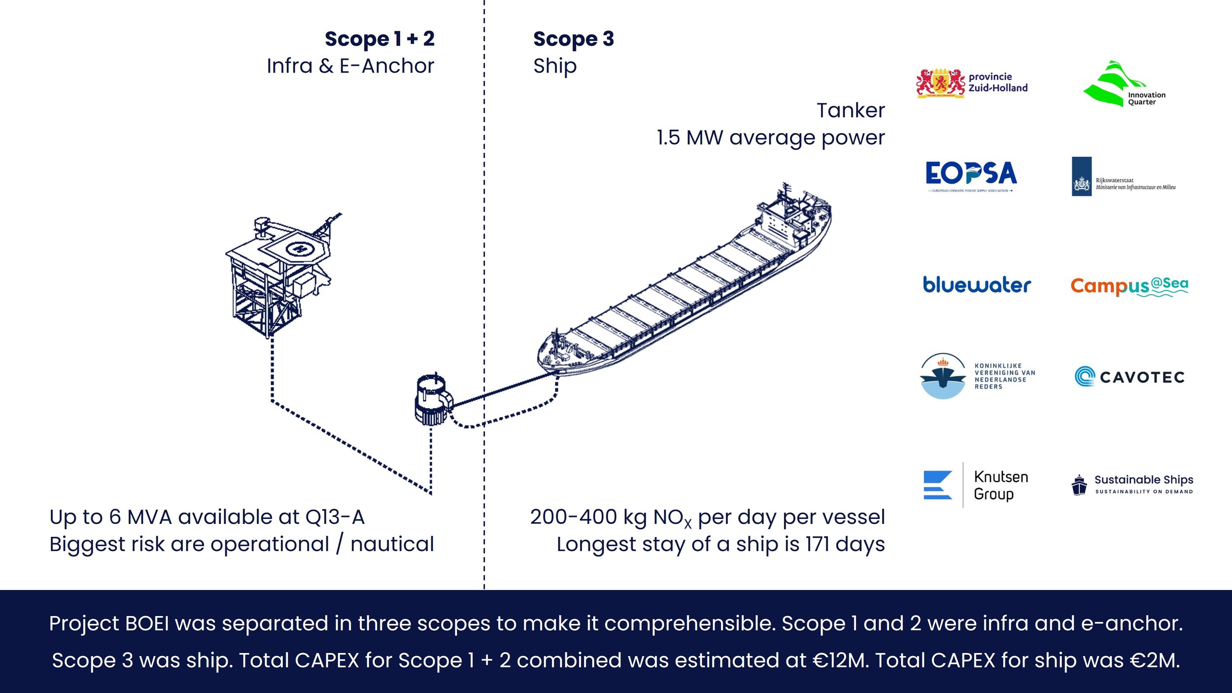
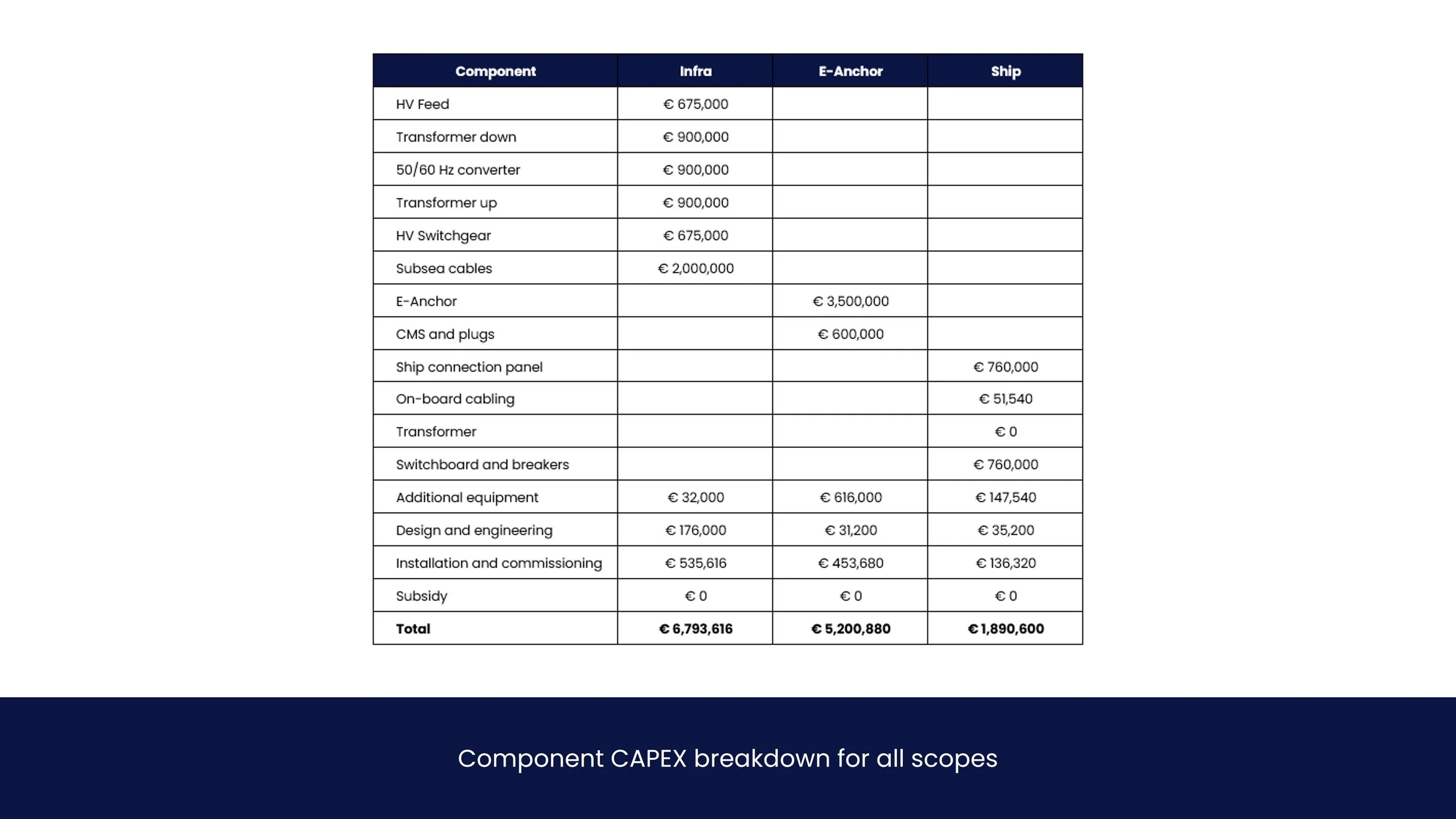
Electrification of a tanker at Scheveningen anchorage is technically and economically feasible. Total costs for all scopes combined is €14M (~€12M for infra and ~€2M for ship). E-anchor and subsea cabling are approximately 50% of all cost.
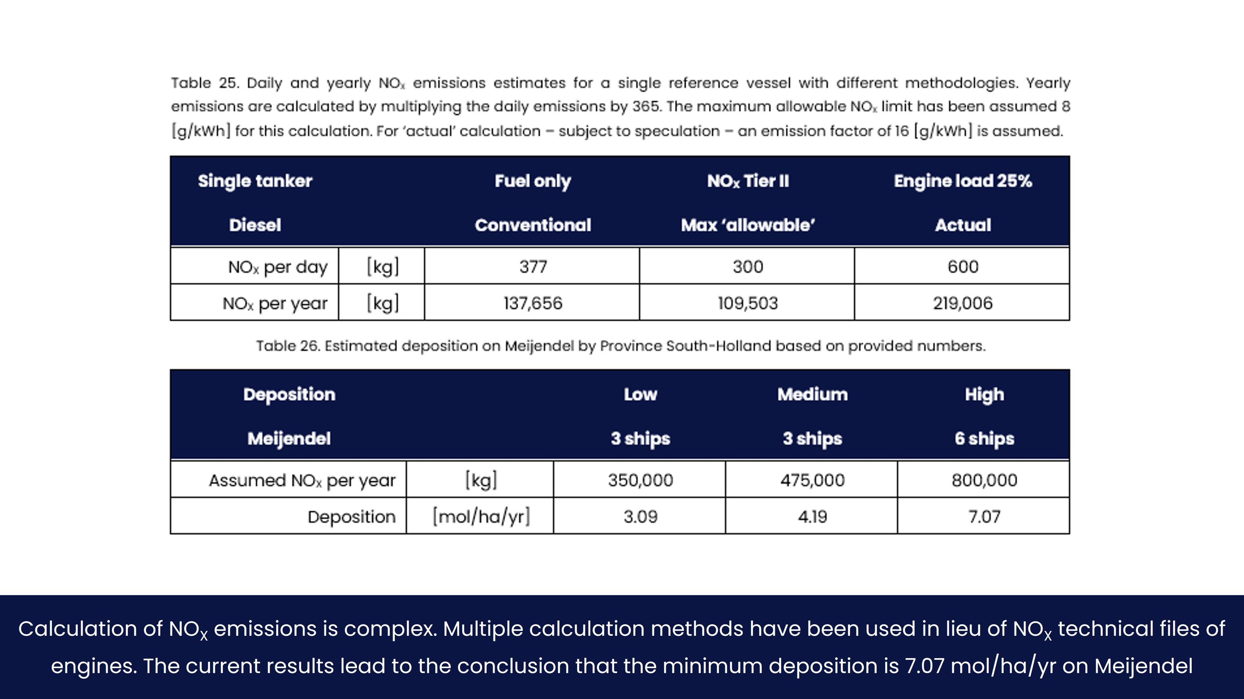
The potential NOx reduction is much higher than initially anticipated. It is estimated at well above 800,000 kg per year for all vessels, equalling ~7.5 mol NOx deposition per ha per year.
Break-even price parity for shipowner and provider of power is at around €0.20-€0.25 per kWh. A feasible business case can be obtained with Renewable Energy Units only, or ~€3M subsidy.
Project Information
Project BOEI (Buoy for Offshore Emission Irradication) is a techno-economic feasibility study on the electrification of tankers at the Scheveningen anchorage. The goal is to identify the most feasible technical solutions and risks, in addition to cost and emissions reduction estimation.
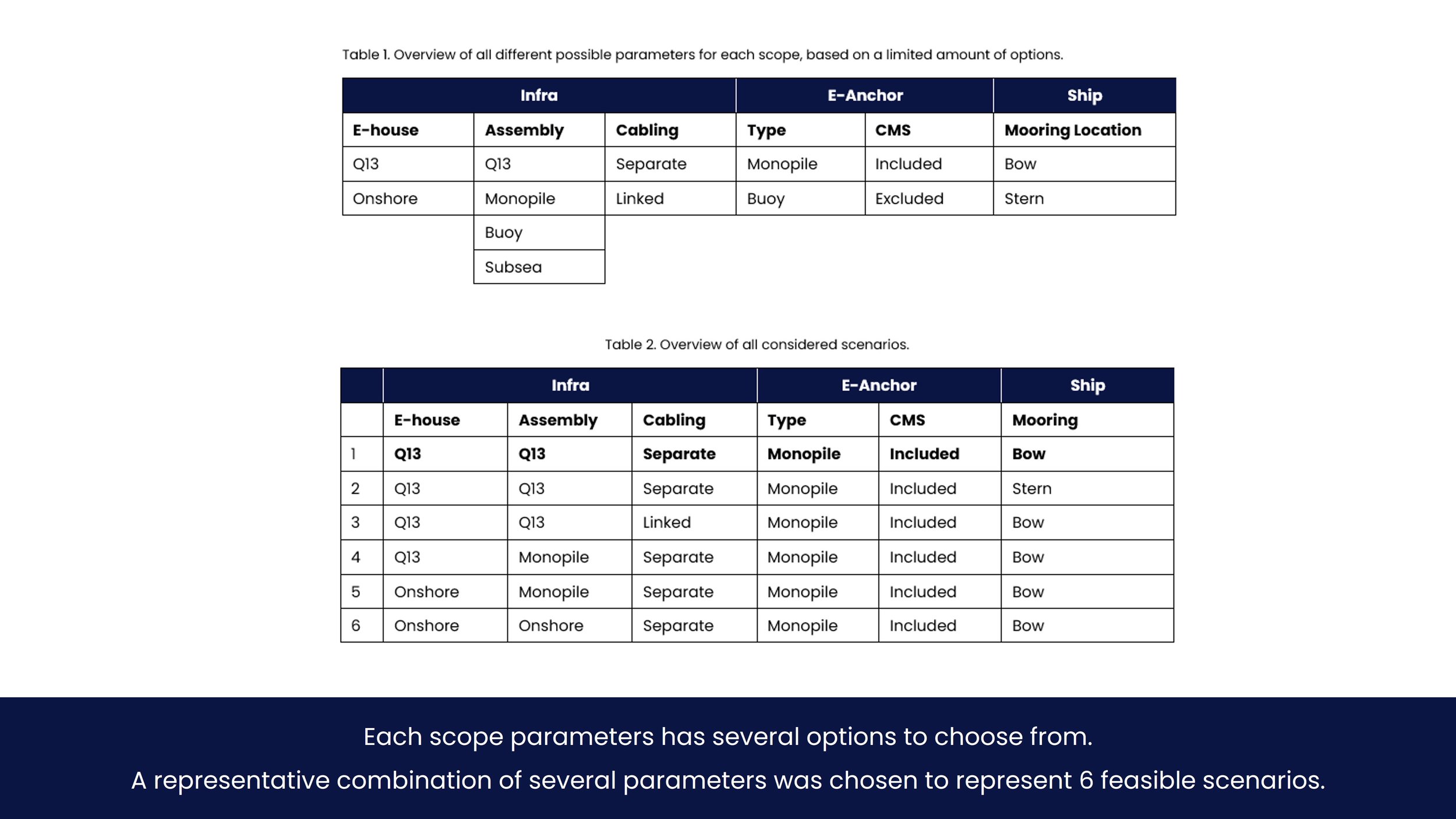
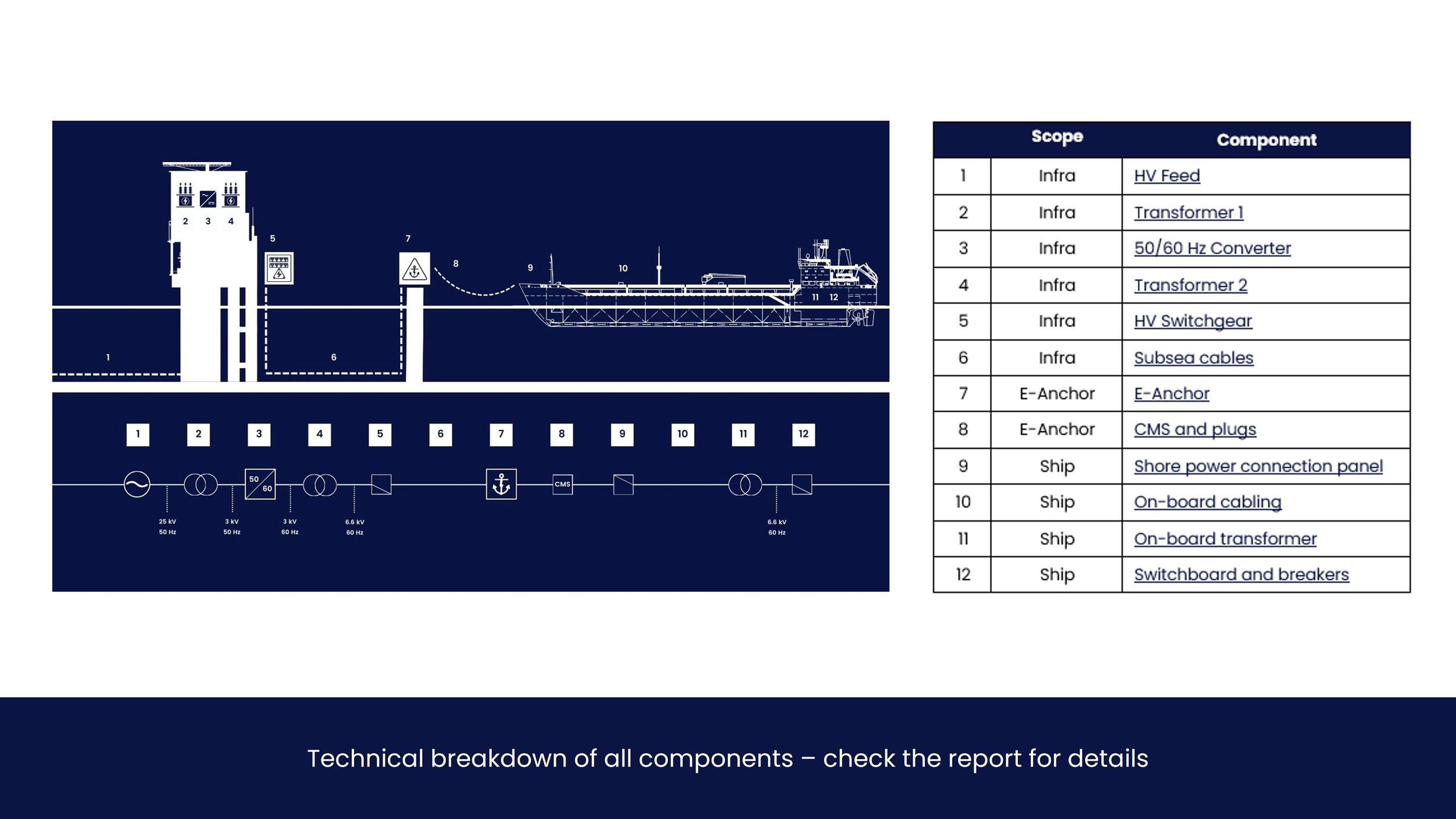
The study is divided into three distinct ‘scope splits’ for both technical and economic reasons, in addition to providing a basis for modelling and division of interfaces. These are scope 1, 2 and 3, representing Infra, E-Anchor and Ship respectively. For each scope, different parameters are identified that allow for different modelling options of the project. The parameters are E-house, Assembly, Cabling, Type, CMS and Mooring Location. For practical reasons, a small selection of scenarios is investigated in this study. The considered scenarios are explored and implemented in the tool to compare different possible outcomes.
-
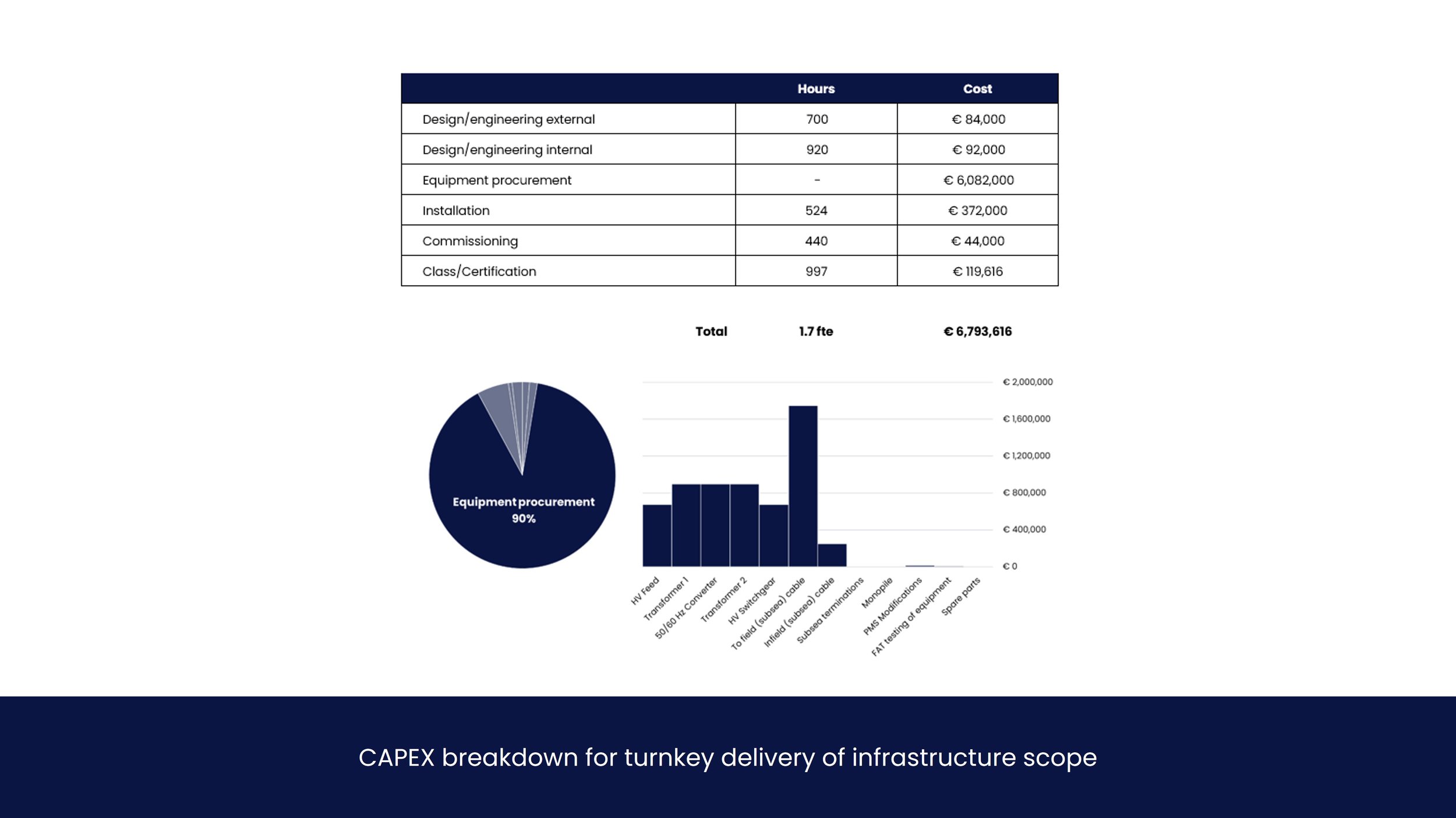
Infra is defined as everything leading up to the e-anchor, including E-house with High Voltage Feed, transformers and converter, high-voltage switchgear that divides power to e-anchor(s), plus cabling of all these components, i.e. the in-field infrastructure. The following requirements apply:
Spare capacity of 6 [MVA] is available at Q13-A, with main switchgear operating at 25 [kV]. There are 2 spare outgoing breakers available as per 2025.
Space on Q13-A is ‘limited’, it is preferred to have as much equipment as possible not installed on the platform. This is contradictory to e-anchor requirements, which do not allow for the installation of power equipment.
There are at least 2 spare J-tubes available for subsea cabling to the e-anchors.
All subsea cabling needs to be trenched to a minimum of 2 meters.
-
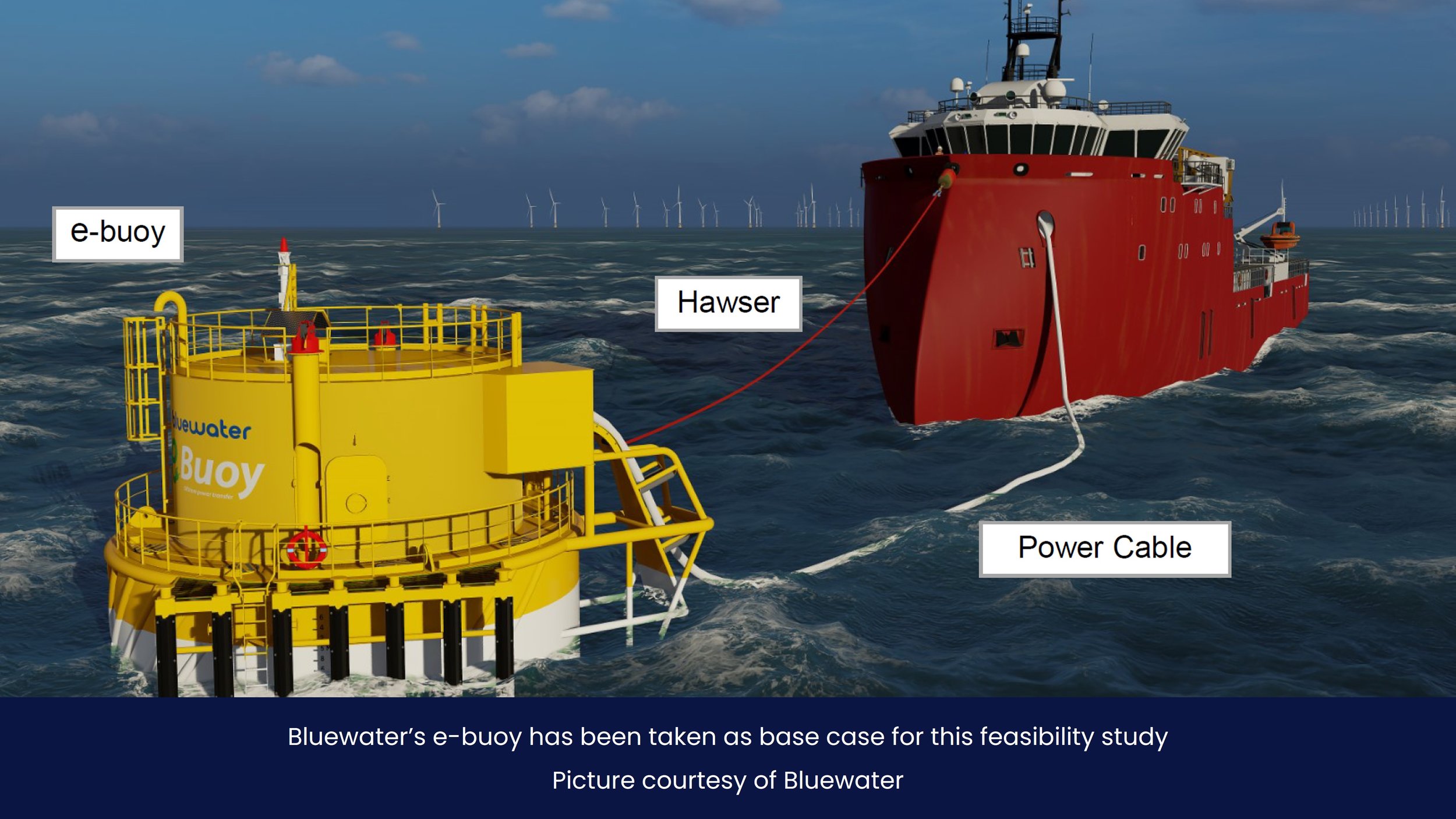
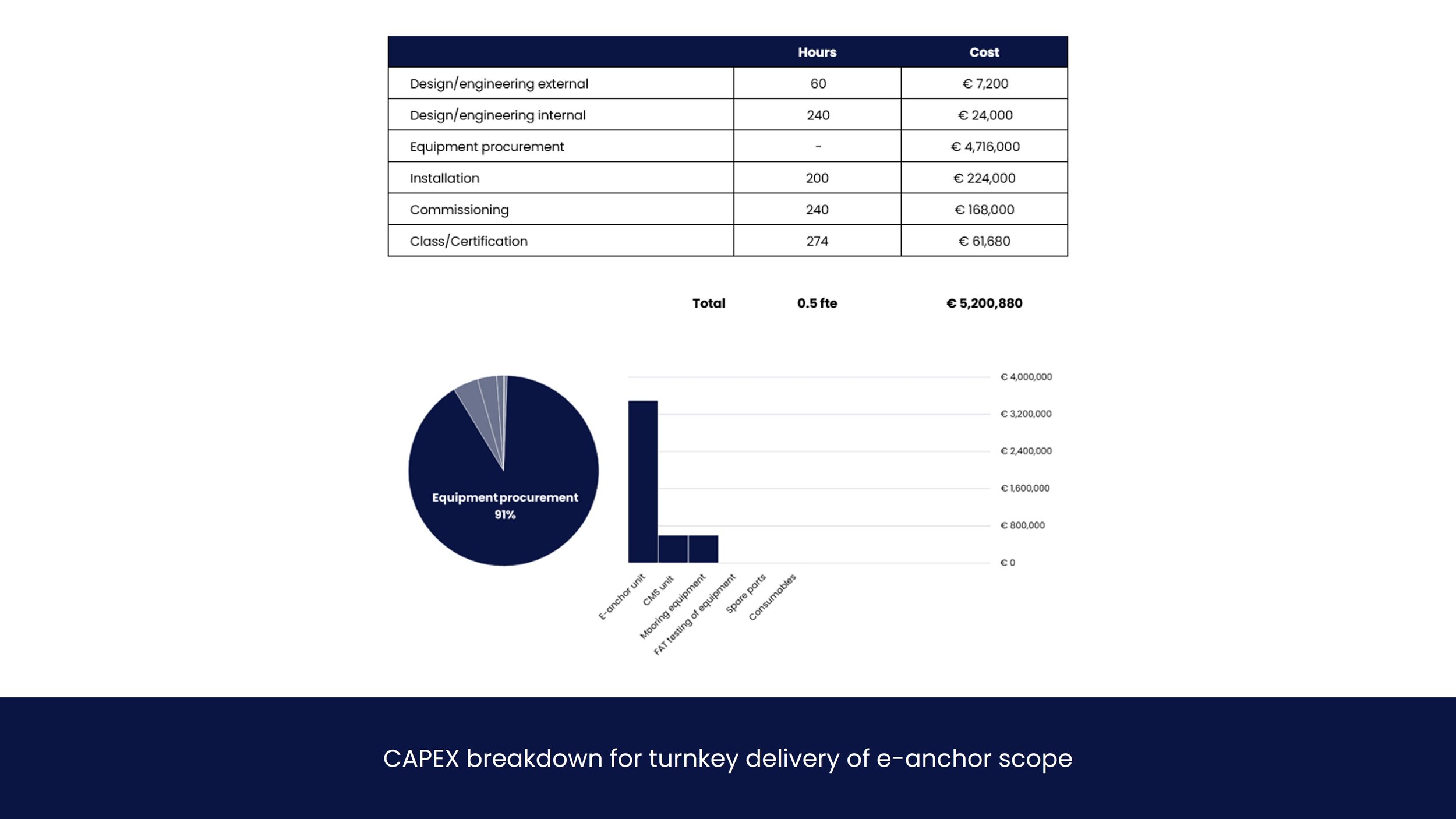
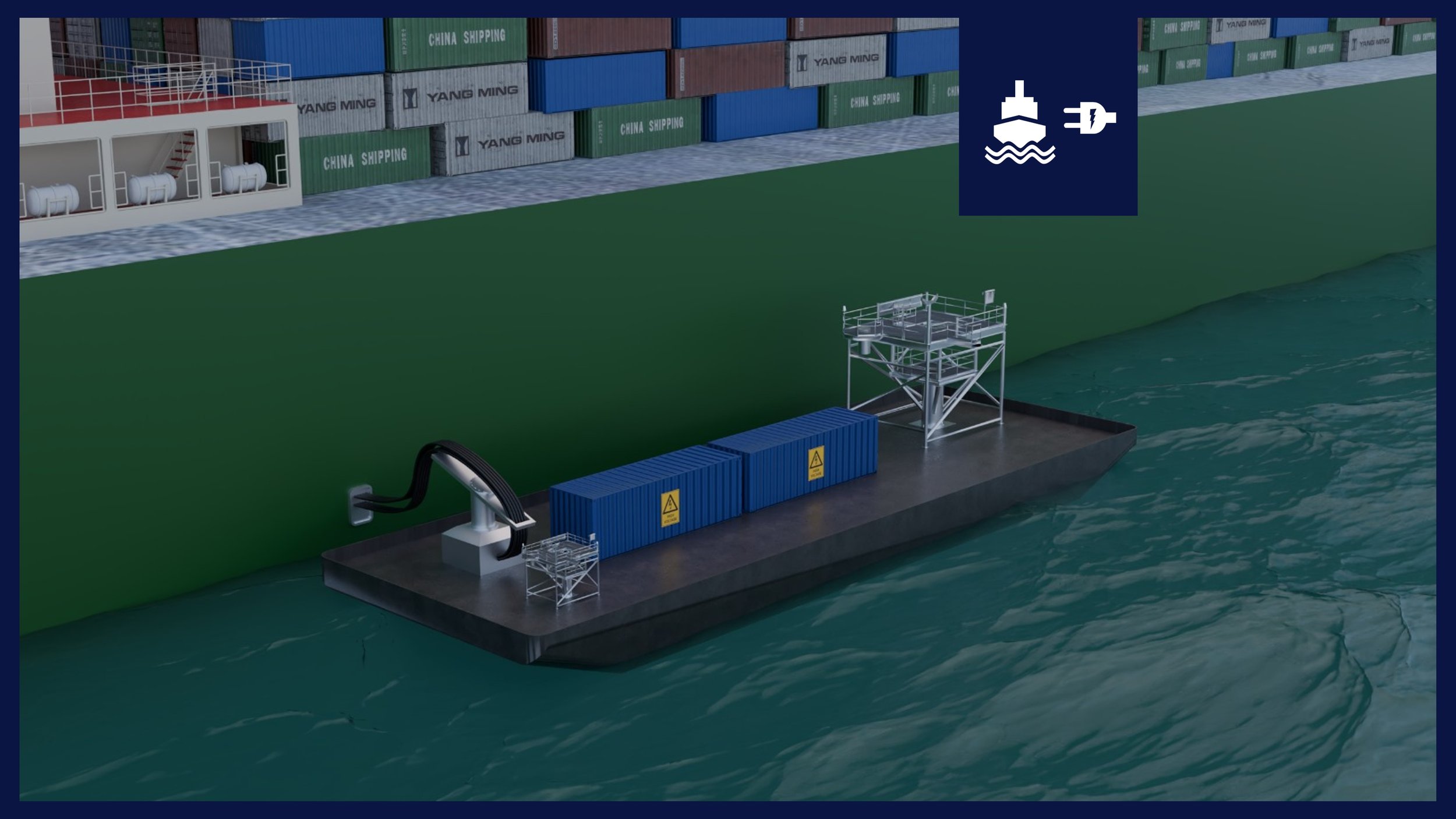
E-Anchor is defined as the electric interface providing power to a vessel, to which the vessel can be moored. The e-anchor can be a buoy or pile, pending on water depth and permitting preferences. For feasibility purposes, there is no functional or cost difference between a pile and a buoy. It is assumed the Cable Management System (CMS) is included in this scope. The following requirements apply:
The Cable Management System (CMS) is to be provided by the e-anchor. The vessel will not have to have a CMS on-board.
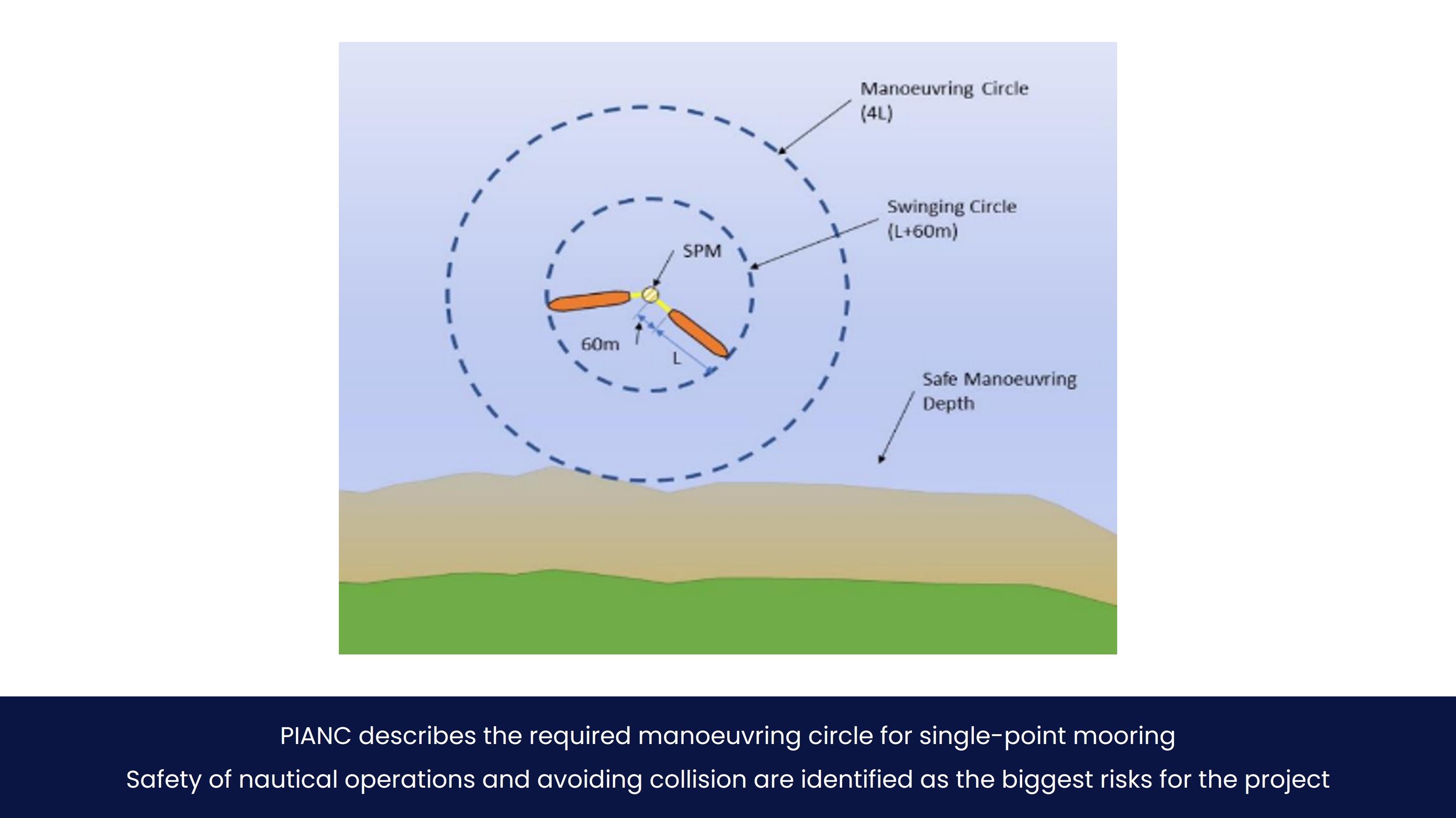
Anchoring areas are circular so that vessels can swivel around the anchor location situated in the middle of the circle.
A minimum radius of ship length (L) plus 60 [m] is required around the e-anchor.
A minimum manoeuvring circle of four time ship length (4L) is required from an operational, mooring and safety perspective.
The e-anchor is not allowed to have transformers or converters installed.
The ship connects to the e-anchor without the need for assisting tugs or the need for personnel to board the e-anchor.
All engineering, calculations and business case analyses will be based on existing technology, as provided by consortium members. This means that:
• maximum allowable voltage is 11 [kV]
• maximum allowable current is 500 [A]
• maximum allowable power is ± 8 [MW]
• Maximum allowable cable size is 240 [mm2]
-
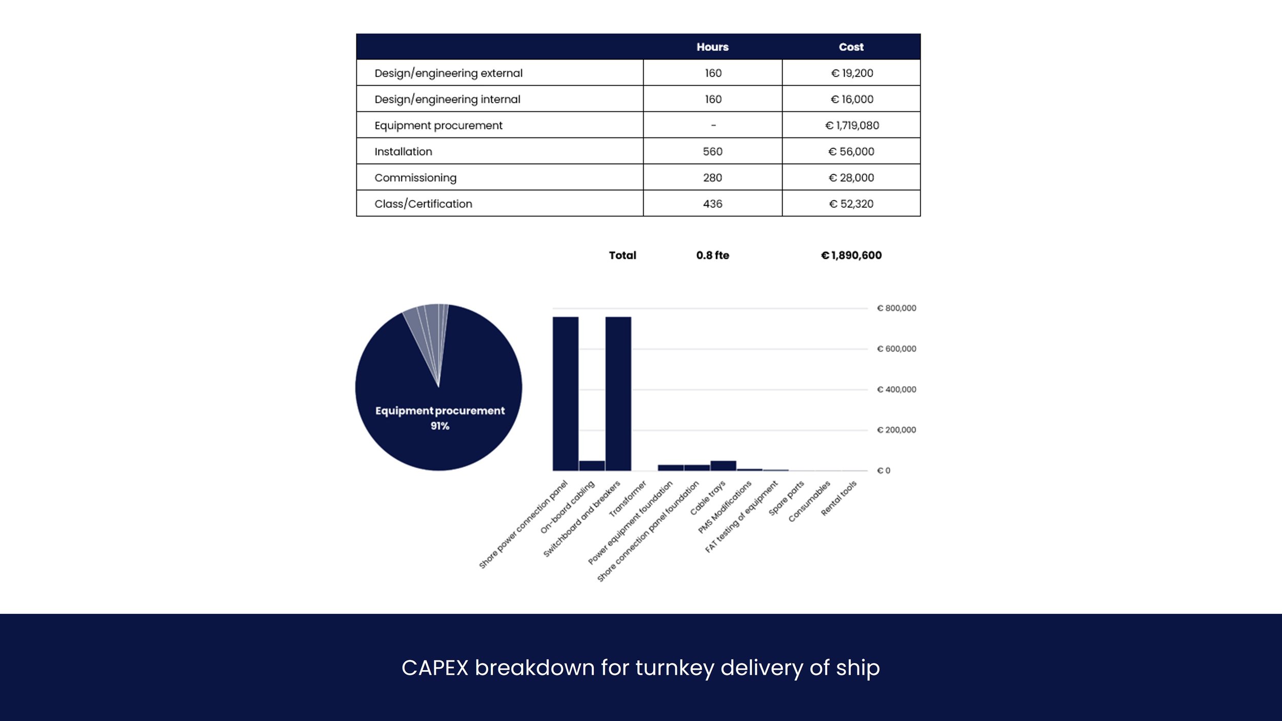
Ship is defined as everything that sails away with the vessel after mooring. This generally includes shore power connection panel, onboard cabling, switchboard modifications and power equipment if needed. The following requirements apply:
Reference vessel average power demand is 1.5 [MW], peak power demand is 2 [MW].
Reference vessel is operating on 60 [Hz].
The maximum wind force at which vessels are moored is Beaufort 7.
Ships and Power Demand
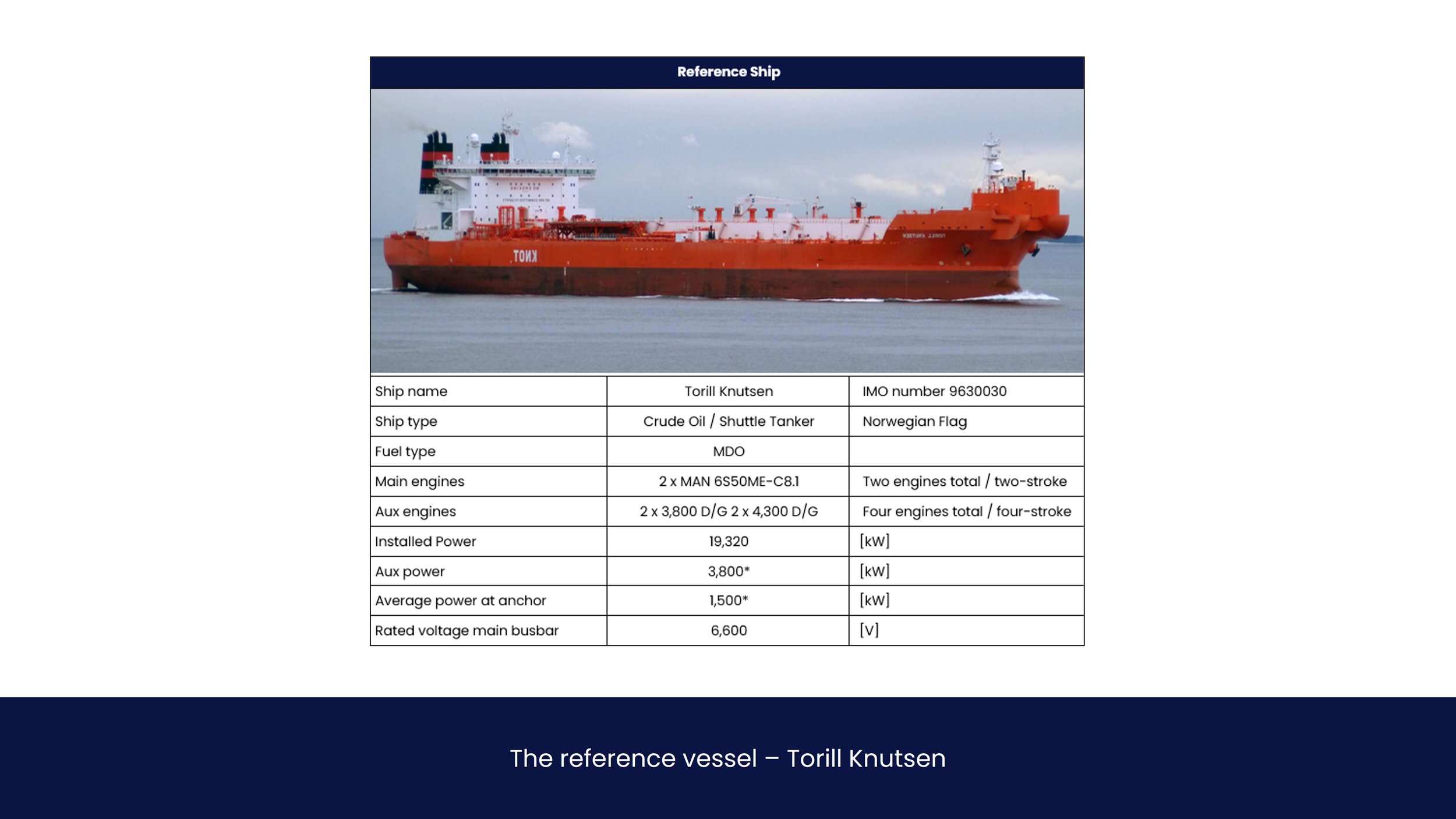
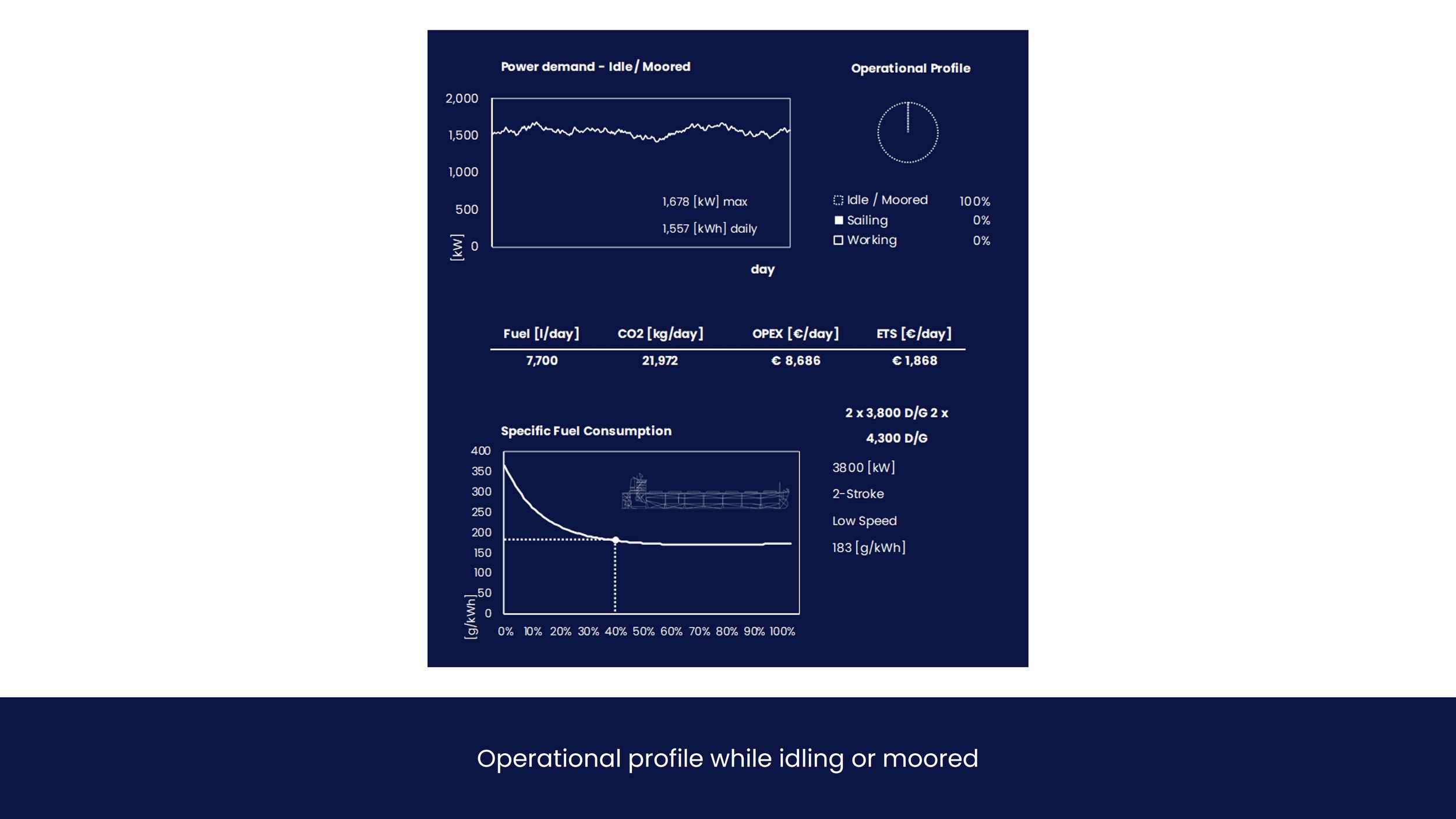
For practical reasons, a single ship is taken as primary reference for this study. As per consortium member Knutsen preferences, the Torill Knutsen is taken as a reference ship. The ship type to which standards and regulations apply is tanker. Average anchor power usually varies between 1,200 and 1,500 [kW]. Aux power is the assumed Installed diesel generator to provide anchor power with a minimum capacity of 3,800 [kW]. Amount of days at anchorage per year is 38 (assumption).
Anchorage
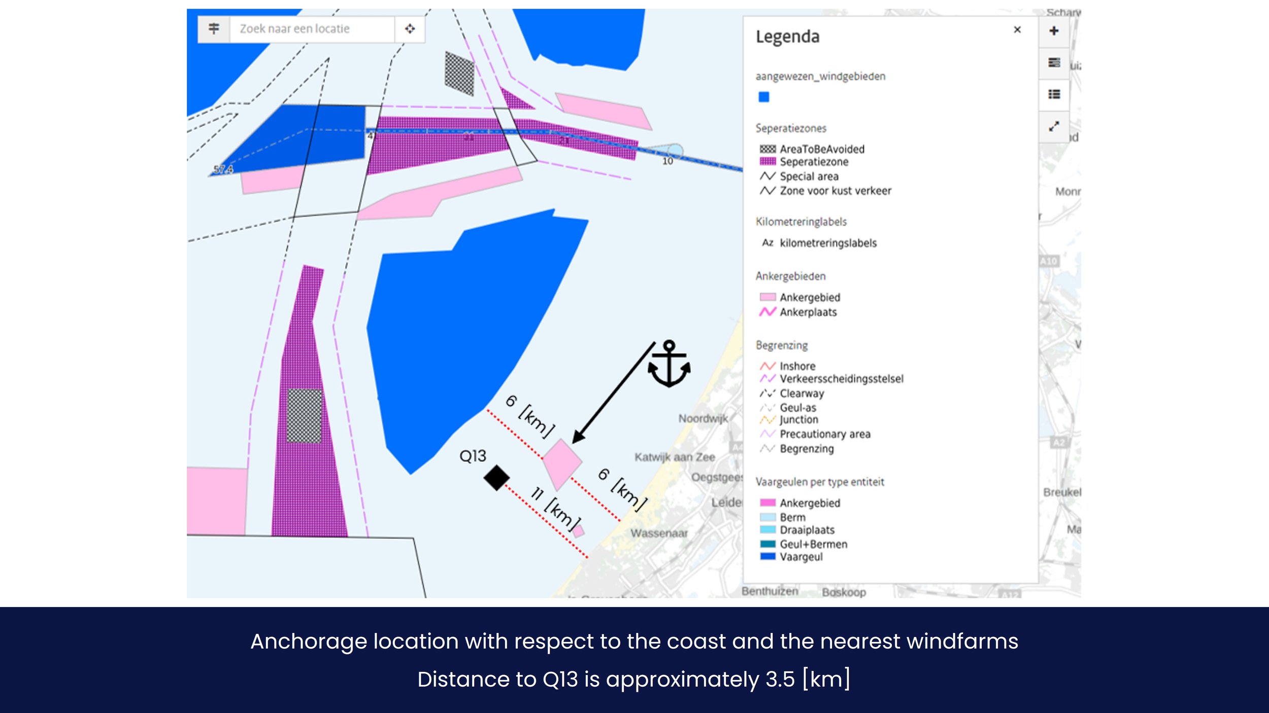
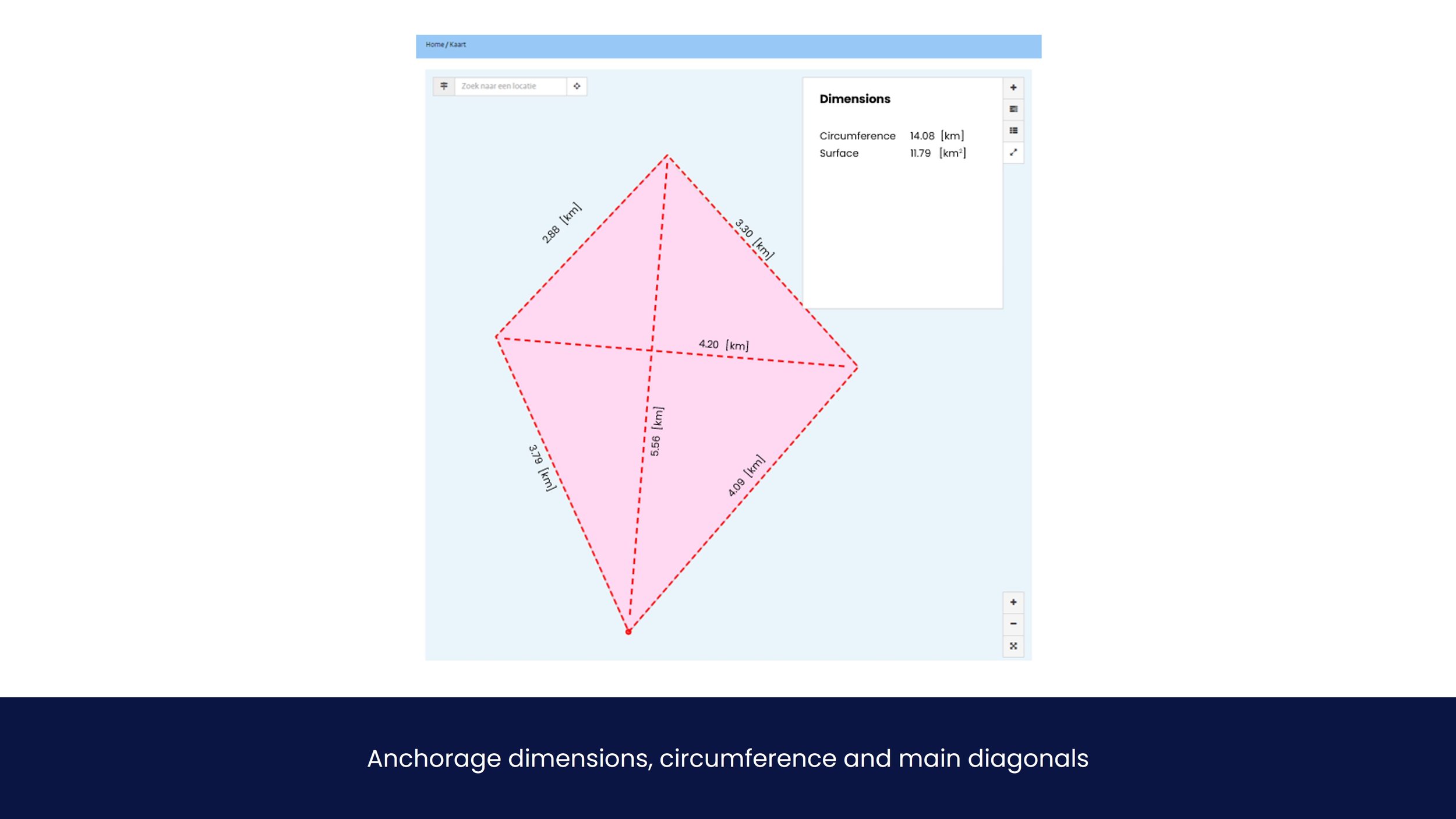
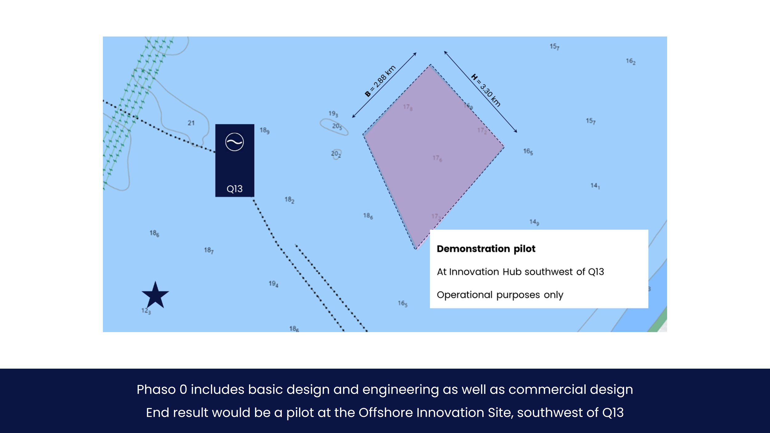
Coordinates of the site and distance to shore and Scheveningen harbour is shown in the figure below, taken from the Nationaal Georegister (NGR), courtesy of Rijkswaterstaat. Another great source is OpenEarth viewer. In addition to bathymetry, this viewer shows windfarms, cables, pipelines and the many other layers. The dimensions are also shown in subsequent figures. The anchoring location has a maximum capacity of 10 vessels.
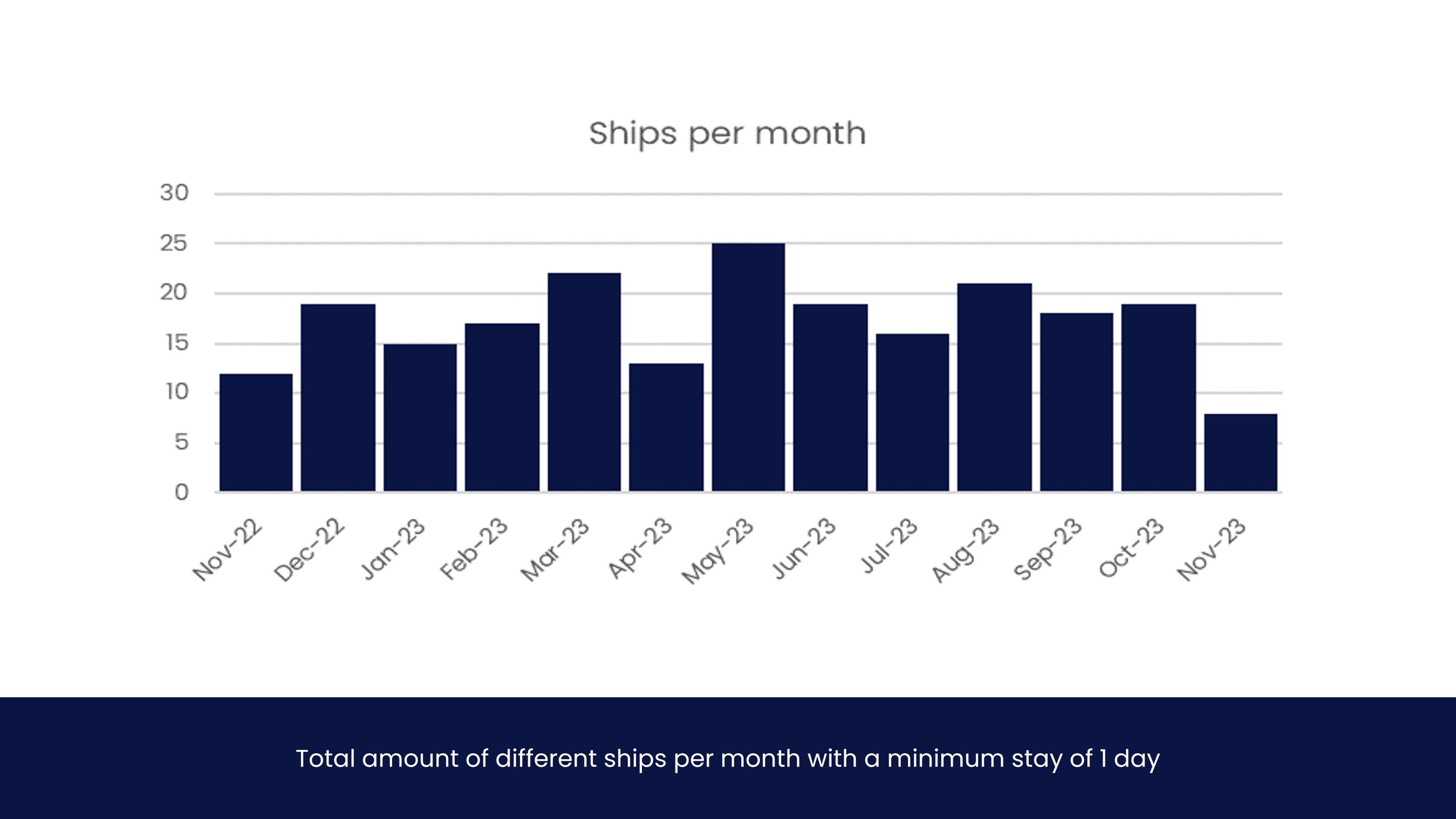
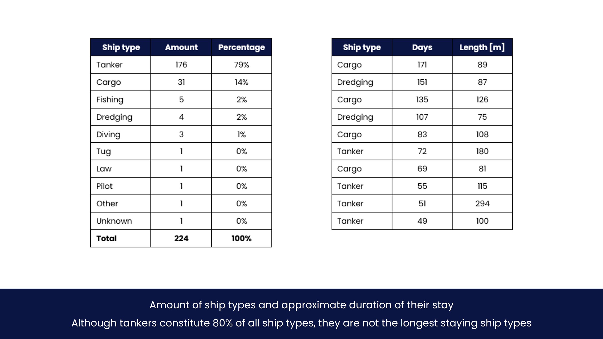
Analysis shows that a total of 224 different ships were moored at anchorage for more than 1 day in 2023. Tanker and cargo ships represented 92% of all these ships, 79% tankers and 14% cargo. On average, 6 ships are moored at any time over the year for an average of 10 days. Tankers are moored 7 days on average. The largest durations at the anchorage were 171 days, 151 days and 135 days. A single one of these three vessels could potentially make the business case.
Technical Scope
This chapter contains a technical description of the entire project, plus the legal requirements and standards that are applicable to the components and operation. The highlights of the chapter are provided below. Check the report for all details.
-
The design lifetime of the system shall be 25 years minimum.
Maintenance of the installation including power losses shall be minimized.
The shore connection shall be suitable for continuous, reliable, safe and easy operation. Reliability rates shall be indicated by the supplier.
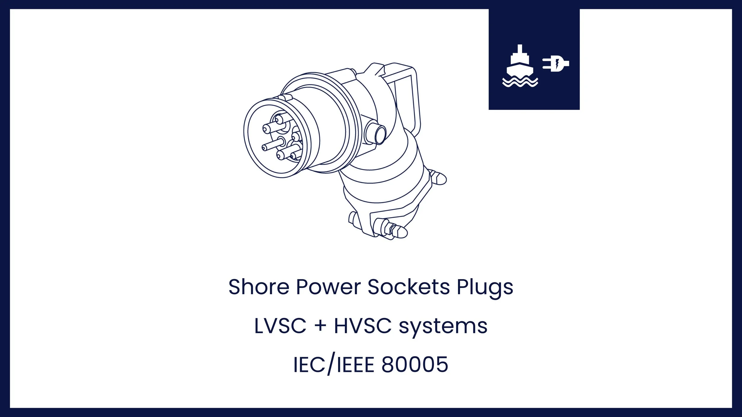
All applicable international and class standards, including national electricity grid code (for Netherlands - Netcode elektriciteit) shall be fulfilled. These apply to all equipment, including but not limited to switch-breakers, connection panels, sockets and plugs, filters, as well as means to limit in-rush current of transformers or large loads energization and subsequent voltage dips if not provided by the onshore power supply.
Equipment shall be suitable for environmental conditions. Effective means shall be provided to prevent corrosion on equipment due to accumulation of moisture and condensation.
An equipotential bonding between ship and ‘shore’ with an earthing electrode is required.
-
NEN-ISO/IEC/IEEE
• NEN-ISO/IEC/IEEE 80005-1: Utility connections in port: HVSC systems – General Requirements High Voltage shore side electricity (up to 20 MVA per vessel).
• NEN-ISO/IEC/IEEE 80005-2: Utility connections in port: HVSC systems – Data communication for monitoring and control.
• NEN-ISO/IEC/IEEE 80005-3: Utility connections in port: HVSC systems – General Requirements Low Voltage shore side (typically less than 1 MVA).
• IEC 62613-1: Plugs, socket-outlets and ship couplers for high-voltage shore connection systems (HVSC Systems) – Part 1: General requirements.
• IEC 62613-2: Plugs, socket-outlets and ship couplers for high-voltage shore connection systems (HVSC-Systems) – Part 2: Dimensional compatibility and interchangeability requirements for accessories to be used by various types of ships.
• IEC 60092-101:2018 – Electrical installations in ships. Part 101: Definitions and general requirements.
• IEC 60092-503:2007 – Electrical installations in ships - Part 503: Special features - AC supply systems with voltages in the range of above 1 kV up to and including 15 kV.
• IEC 61363-1: Electrical installations of ships and mobile and fixed offshore units - Procedures for calculating short-circuit currents in three-phase AC.
• Codes, standards and guidelines for safety when working in dangerous zones are shown in 3.6.2.
DNV / Lloyd’s
• DNV-RU-SHIP Pt.6 Ch.7 section 5 - Environmental protection and pollution control - Electrical shore connections – Shore Power
• DNV-RU-SHIP Pt.4 Ch.8 – Electrical Installations
• DNV-RU-SHIP Pt.6 Ch.2 – Propulsion, power generation and auxiliary systems
• LR Rules and Regulations for the Classification of Ships, July 2019 - Part 6 - Control, Electrical, Refrigeration and Fire – Chapter 1 Control Engineering Systems
• LR Rules and Regulations for the Classification of Ships, July 2019 - Part 6 - Control, Electrical, Refrigeration and Fire – Chapter 2 Electrical Engineering
• LR Rules and Regulations for the Classification of Ships, July 2019 - Part 7 - Other Ship Types and Systems - Chapter 13 On-shore Power Supplies
-
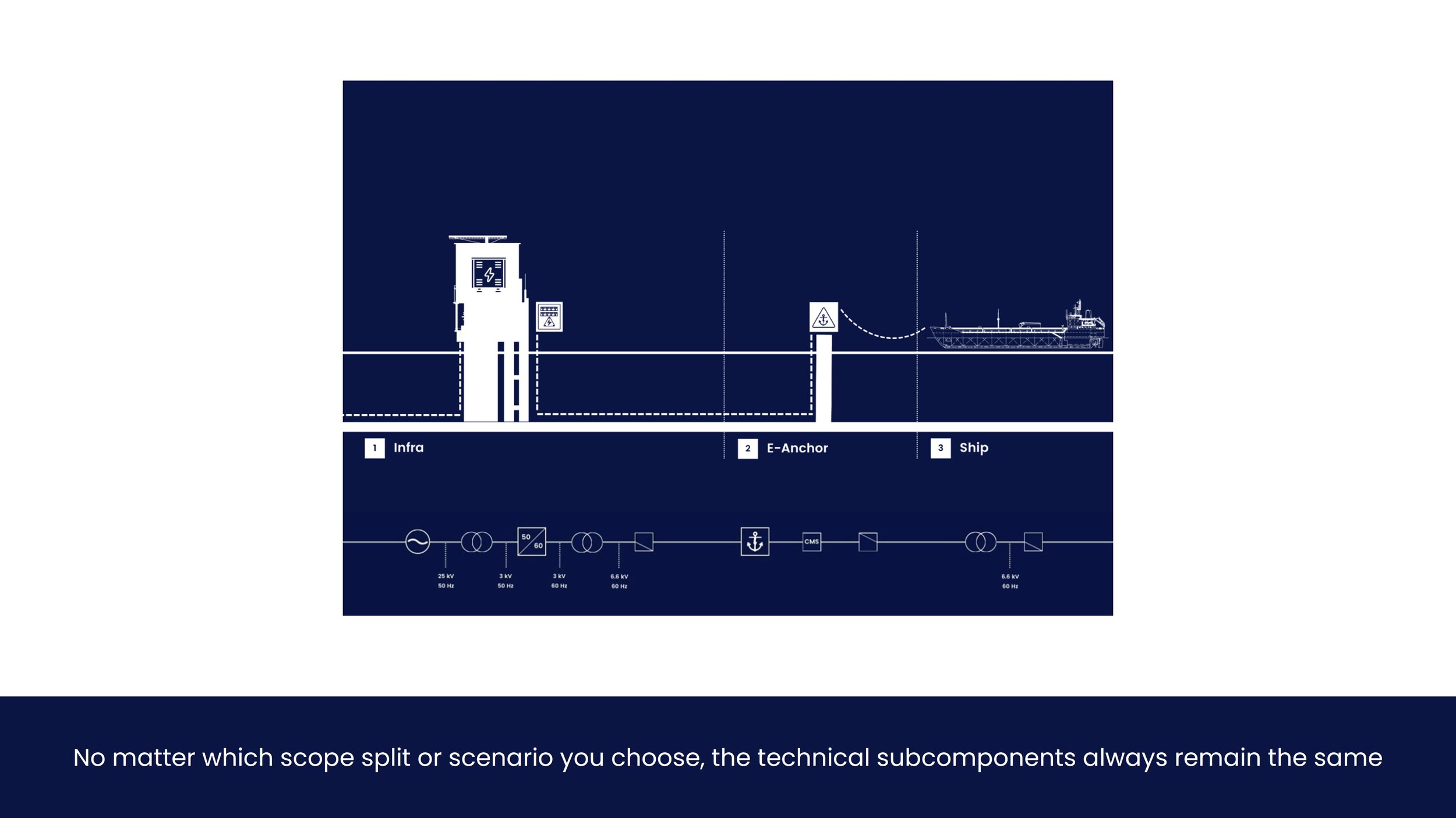
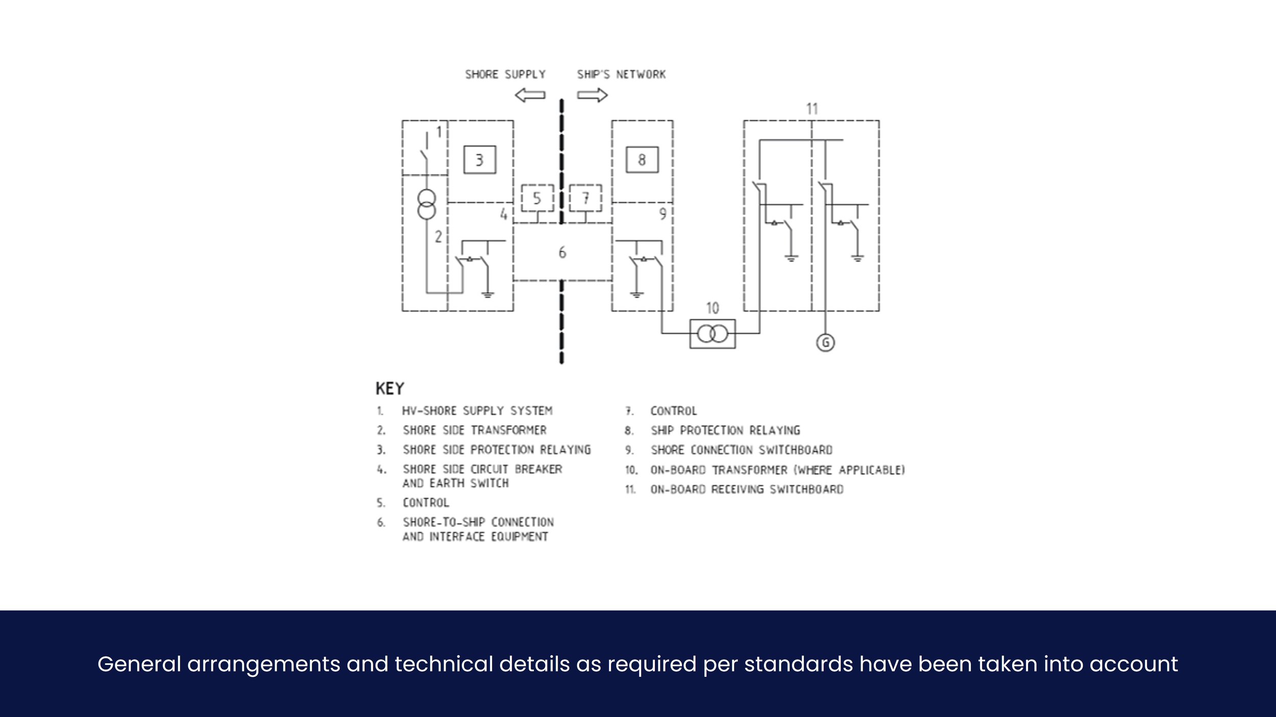
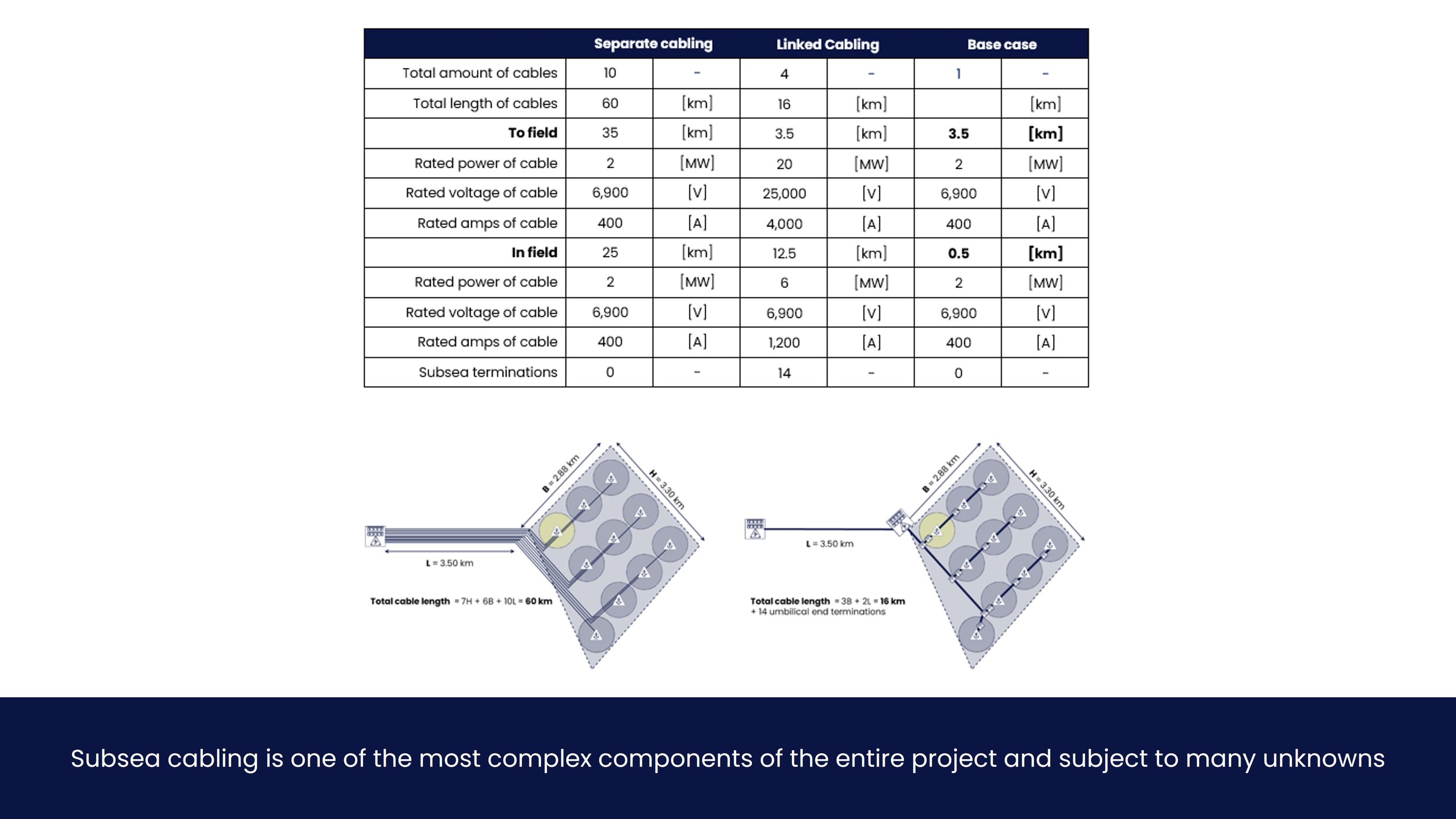
For the sake of clarity, a simplification of the entire technical scope is provided in the figure below. This schematic shows all identified components required to provide power to a single ship. Each components is elaborated upon in the report.
-
Control logic ensures safe operation and monitoring of the entire system. It is described by several governing standards, most importantly IEC/IEEE 800005-2. In this study, it is divided into four sections: (1) protection, monitoring and communication, (2) switchover philosophy (3) alarms and associated safeguards and (4) short circuit or selectivity study.
(1) Protection, monitoring and communication
Protection, monitoring and communication requirements are described in several international and class standards, foremost IEC/IEEE 80005-1 and 2. All communication of ship systems and shore side needs to be compatible with existing ship systems. Communication can be achieved by means of separate fibre optic cables, via the power cable or wirelessly. A list of communication signals that needs to be transmitted and exchanged between the onshore station and the ship is to be provided for the Design Statement by the equipment supplier according to standards and class, of which more can be found in the report.
(2) Switchover philosophy
There are two alternative switchover options: the blackout principle (going ‘through the dark’) and the synchronization principle. These are described by IEC/IEEE 80005-1 under electrical load transfer, section 9.2 and 9.3, summarized in the report in section 3.4.2. For this study, it is assumed load transfer occurs via the synchronization principle, as it is the most stringent switchover procedure. The operational aspects of mooring to a single point mooring with the vessel itself, and taking the power cable onboard, are described in section 3.6.4 of the report.
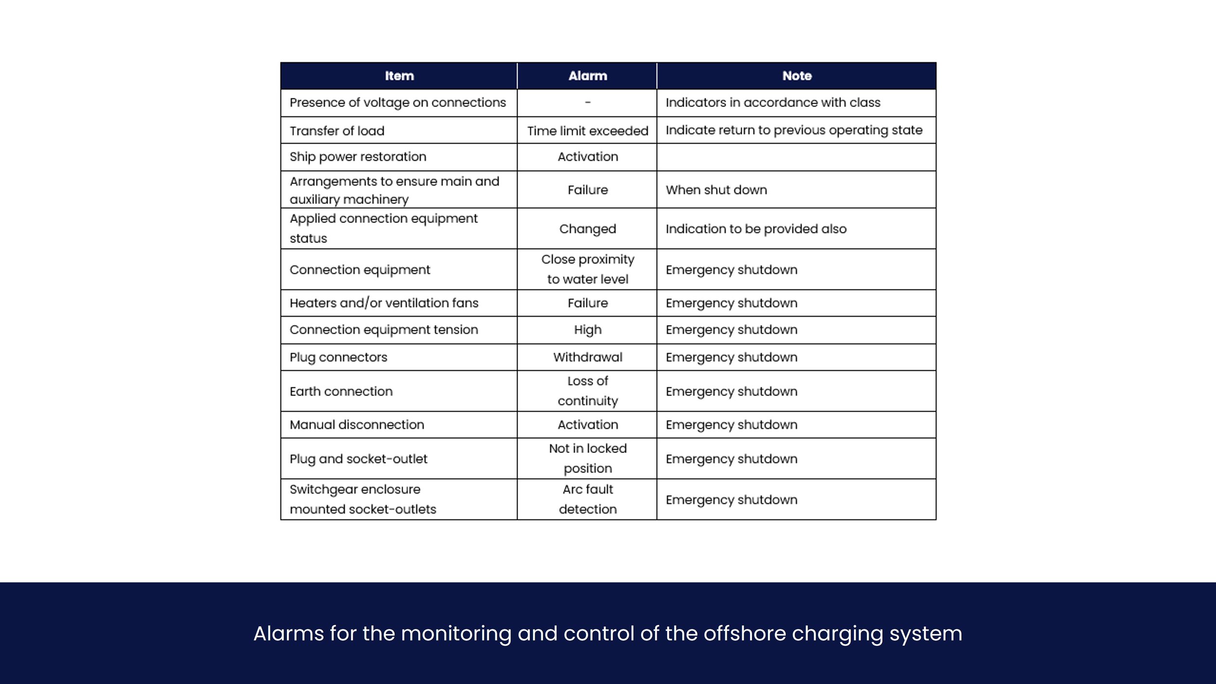
(3) Alarms and associated safeguards
Below is a table with standard alarms and safeguarding measures which are to be installed for monitoring the installation. Emergency ship power restoration in the case of a failure of the HV feed supply is described in IEC/IEEE 80005-1 section 8.6. Not all of these alarms would be suitable to the design, e.g. the close proximity to water level alarm.
(4) Short Circuit or Selectivity study
A short circuit or selectivity study is to be performed according to IEC 61363 standards or similar in order to evaluate functionality of the vessel’s protective devices, such as relays, fuses, and circuit breakers, and the circuits they protect, when shore power modifications are made.
Complete selectivity means that the protective devices will minimize the effect of a short circuit or other undesirable events on the power system. In any case, critical ship systems are to be protected in the case of a short circuit due to any reason (whether it is shore power or not). This study is outside the scope of this feasibility study.
-
This chapter provides a summary of key rules and regulations with regards to shore power. It is broken down into global (IMO), international (EU), regional (Netherlands or Port) and energy majors (e.g. Ørsted). Due to the nature of rules and regulations plus the uncertainty involved, the state of affairs at the time the reader reads this document might differ from the state of affairs at writing.
Shore power mandatory
Shore power will become mandatory in EU and US by 2030, as per FuelEU and Clean Shipping Act . It only applies to vessels of 400 GT and above, but would require all vessels who are currently being build and planned for operation in the EU to have shore power capabilities. It is expected 90% of all port calls in the EU will have to be electrified. Short stays below 2 hours are likely exempt in EU.
The PAS regulations on nitrogen in the Netherlands are a significant motivator for this feasibility study and aim for 80% nitrogen reduction or more. In addition to this stringent requirement, subsidies have been made available to incentivize the reduction of nitrogen. More on this topic is provided in section 5.3.
Apart from governmental organization, many shipowners’ clients are pushing for net zero operations, most notably Ørsted. These organizations are actively pursuing electrification of ships offshore and building e-buoys at windfarms.
Business case improvement by incentives
Carbon tax in the EU (EU ETS) will improve the business case for shore power. With a price of €100 per mT CO2, fuel prices will effectively be doubled. This provides clear incentives for the shipowners to ensure shore power compatibility.
The Netherlands allows the sell of ‘Renewable Fuel Units’ (Hernieuwbare Brandstof Eenheden or HBEs). This will effectively add €0.20 revenue per kWh for shore power in the case of green energy, greatly benefitting the business case.
Ports
A significant portion of major ports around the world have signed shore power declarations to ‘deploy shore-side electricity by 2028 where possible.
Most ports have the ambition to become carbon neutral by 2050.
Cruise and container vessels are the primary target for most ports.
-
Four key aspects in terms of Health, Safety and Environment have been identified with respect to the electrification of vessels offshore. These are listed below and elaborated upon in detail in the subsequent sections. Emissions are discussed in more detail in chapter 4.3 of the report.
1. Handling of high voltage equipment by personnel
2. ATEX zones onboard the vessel
3. Mooring, nautical and operational aspects
4. Switchover procedure
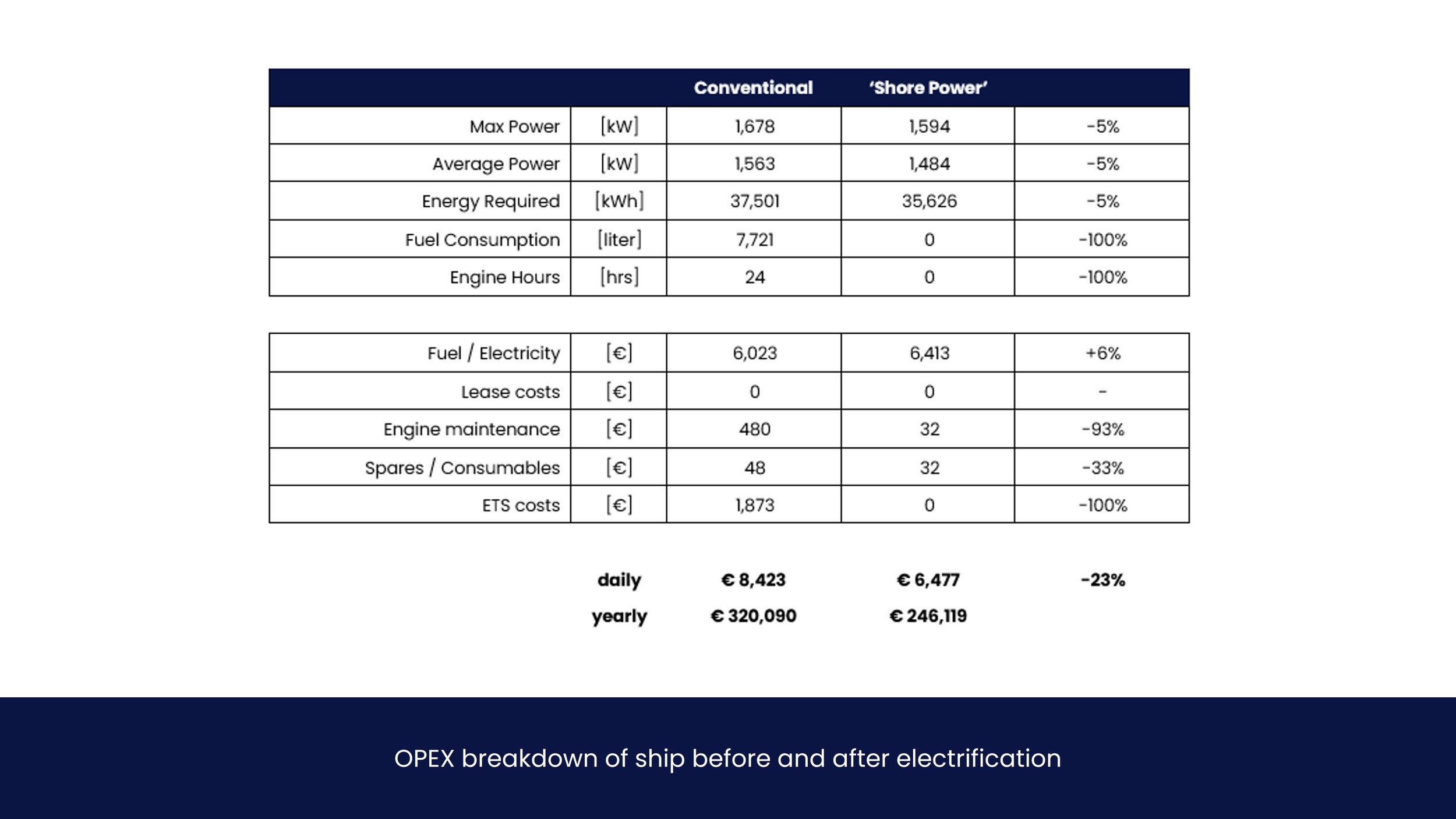
Results
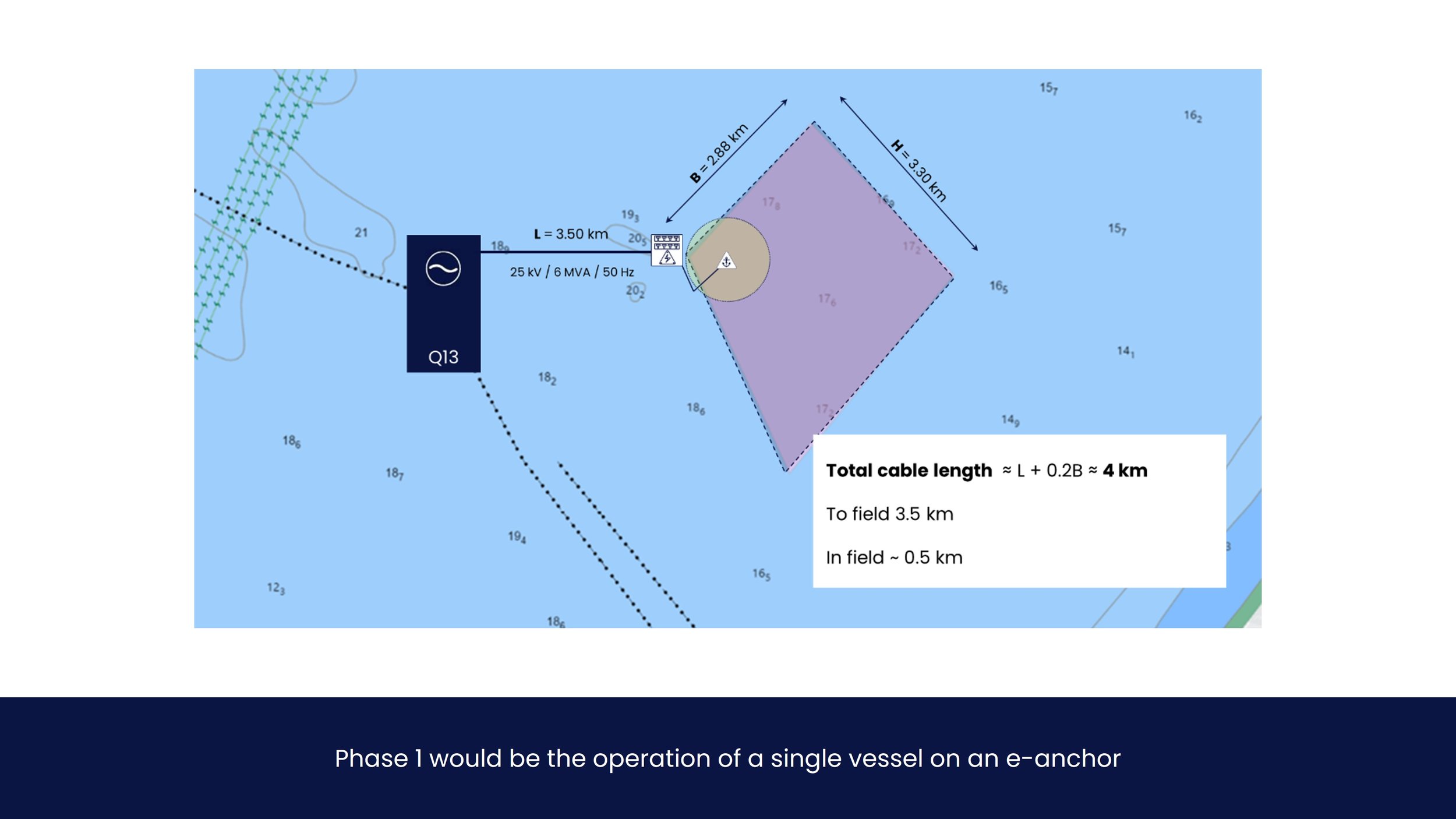
This chapter contains CAPEX and OPEX indications for the different scopes, emission calculations (in particular NOX), key risks and mitigations, as well as a proposed organizational way forward, of which a planning for project development is most important. Costs are determined via ‘turnkey delivery’ principle, each scope accounting for design and engineering, equipment procurement, installation and commissioning. Results shown are for a single e-anchor and ship, i.e. phase 1.
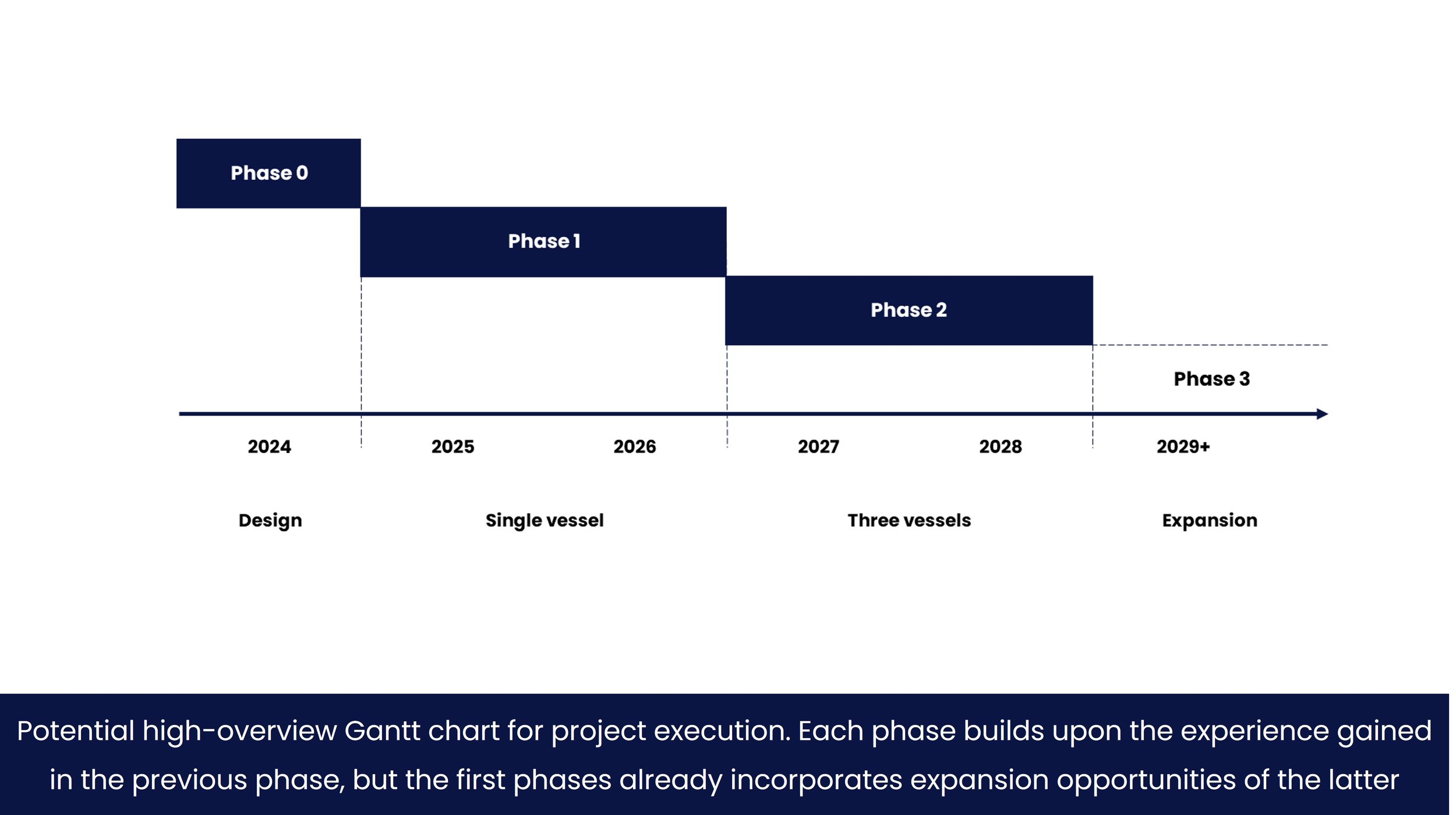
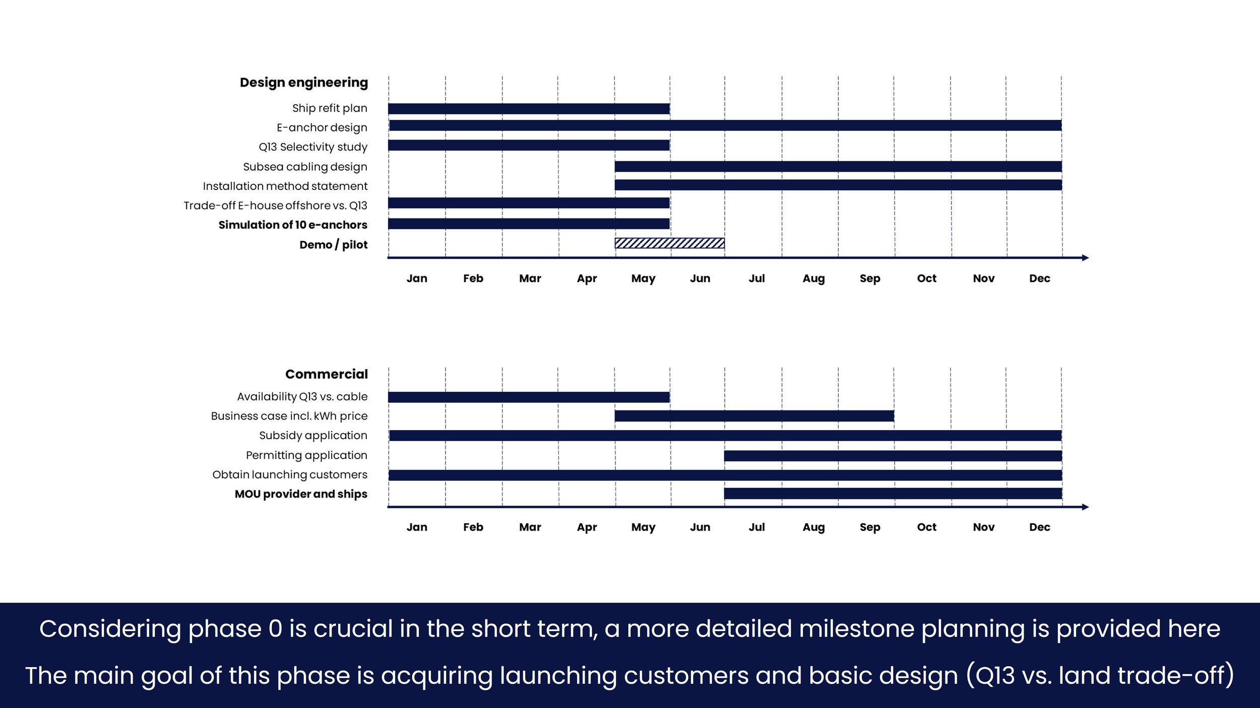
Planning
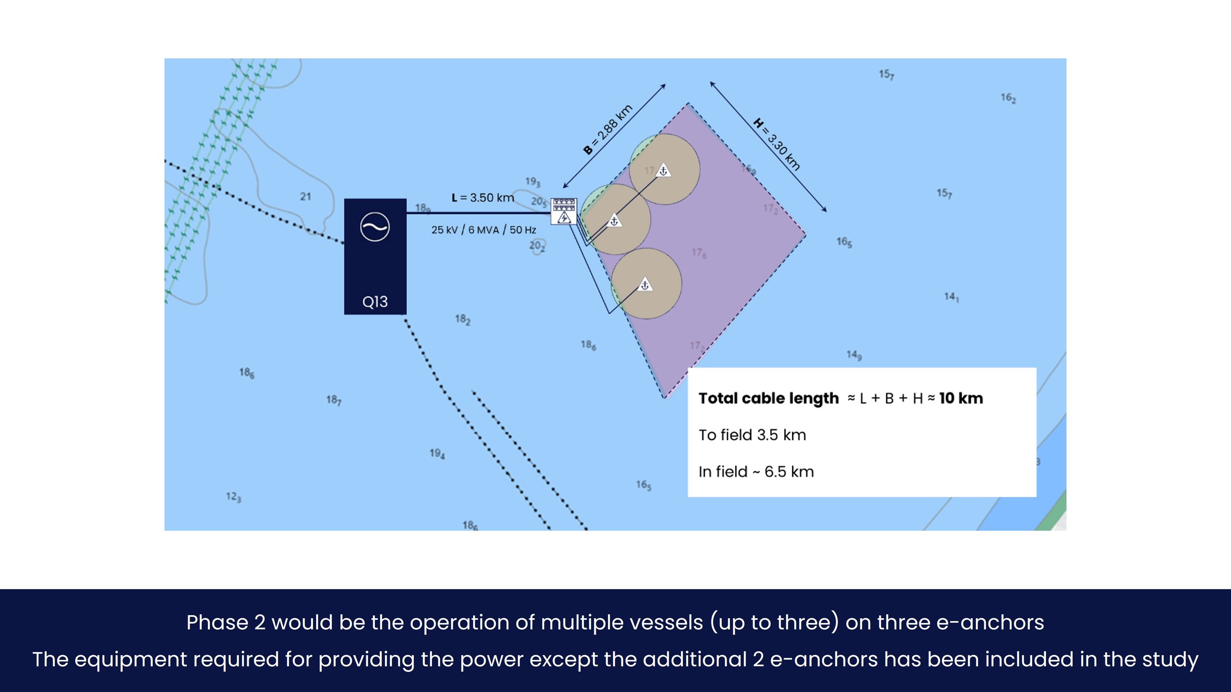
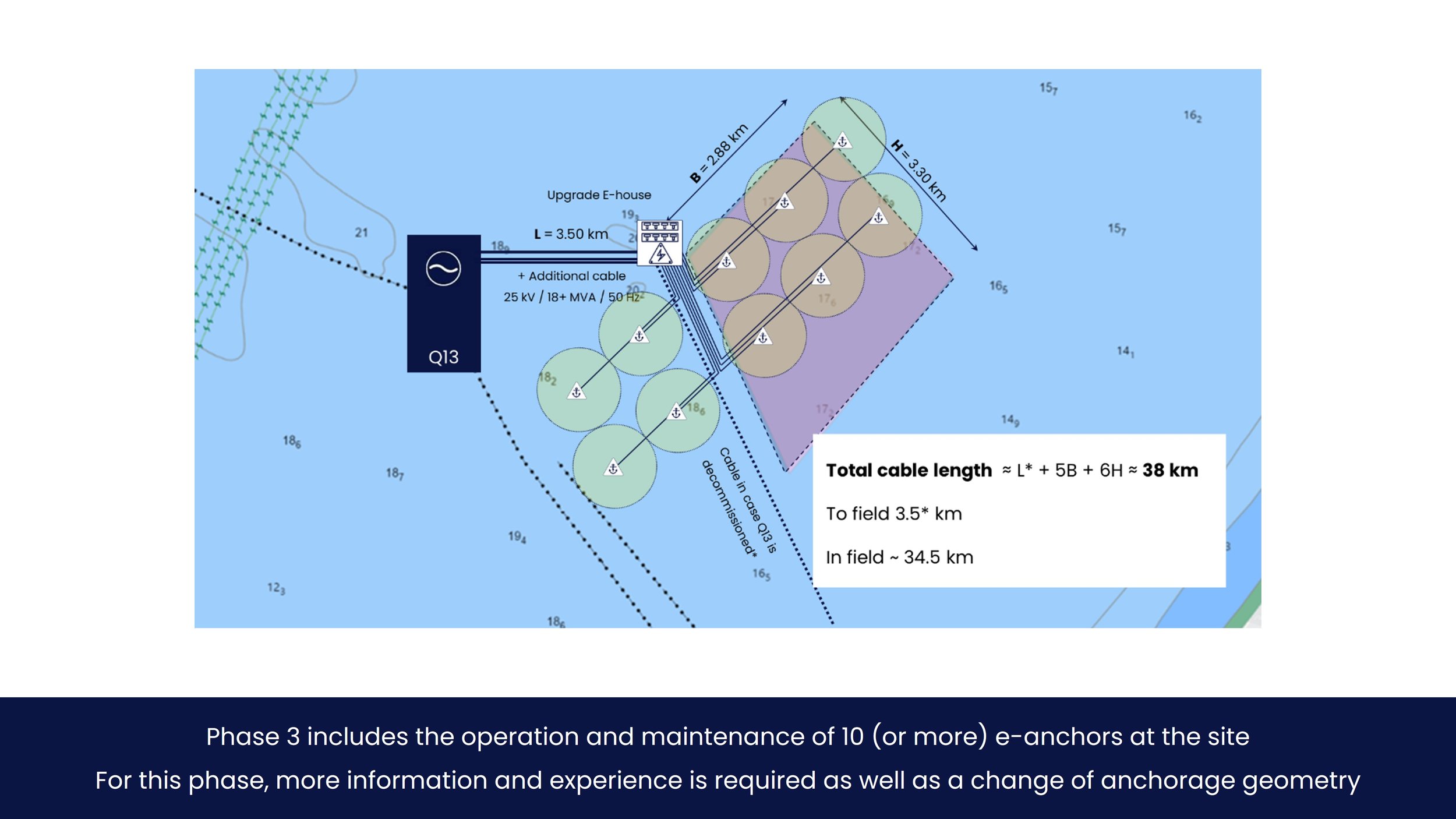
For a realistic project execution, it is recommended to brake down the project into three distinct phases. These execution phases are preceded by a design phase required for FID. For this planning, scenario 4 is assumed as base case. That means power is initially provided by Q13 – enough for phase 1 and 2 – and converted in an E-house situated on a monopile next to the anchoring area. At least twice the amount of power will have to be made available for phase 3. It is uncertain where the power will come from, Q13 or land.
You might also like


This case study determines the cost of generating electricity onboard a ship using auxiliary diesel engines to determine when it is more cost-effective to purchase electricity from the grid in port. Results show that fuel costs alone sit around $0.20 per kWh, but once regulatory compliance costs are layered on top, the total effective costs rise sharply to $1.00 per kWh by 2040.