Ship-Based Carbon Capture Techno-Economic Guide
Determine operational and economic impact for carbon capture onboard your ship
This blog provides techno-economic guidance for the use of Ship-Based Carbon Capture (SBCC) onboard your vessel, including explanation on how it works, operational impact, logistics and of course the costs for implementation. All assumptions, numbers and figures are based on 11 case studies, available for download here.
SBCC is applicable to virtually all ship types, sizes, and fuel - LNG is cheapest
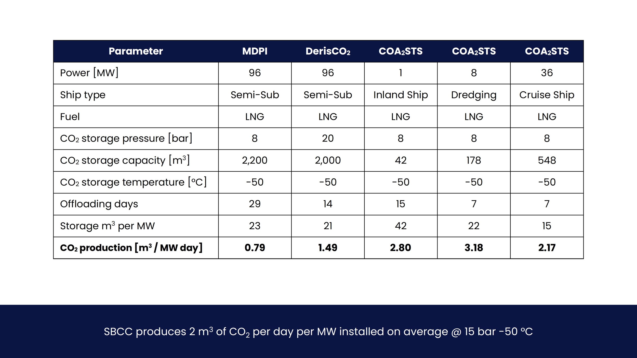
SBCC produces 2 m3 of CO2 per day per MW on average @ 15 bar -50 °C
SBCC is CAPEX dominated and costs €175k per MW or €115 per mT CO2
Download premium E-book + Data
Purchase the E-book to obtain all data
Make your own analyses and keep a copy for yourself - forever!
Land-Based Carbon Capture and Storage (CCS)
Carbon Capture and Storage, commonly referred to as CCS, refers to the collecting and storing of carbon dioxide (CO2) from exhaust gasses before it is released into the atmosphere.
CCS technology has been in operation since 1972 in the US, where several natural gas plants in Texas have captured and stored more than 200 million tons of CO2. Existing technology can recover up to 90% of CO2 emissions from burning fossil fuels in power generation and industrial operations.
For large scale CO2 land-based capture processes, levelized cost of CO2 capture is currently estimated at approximately 60-100 €/ton CO2, based on several front-end engineering design studies on full scale plants.
-
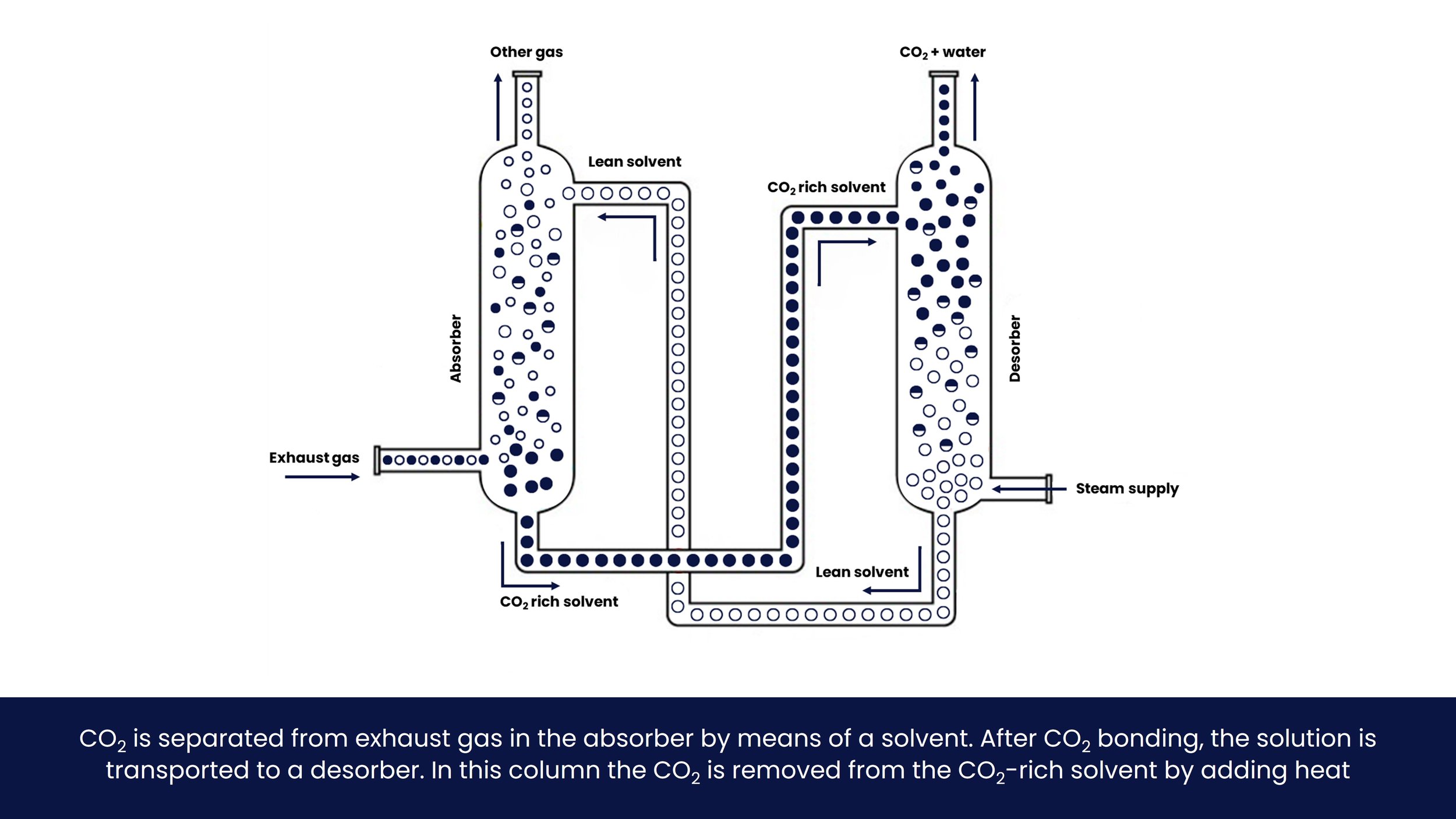
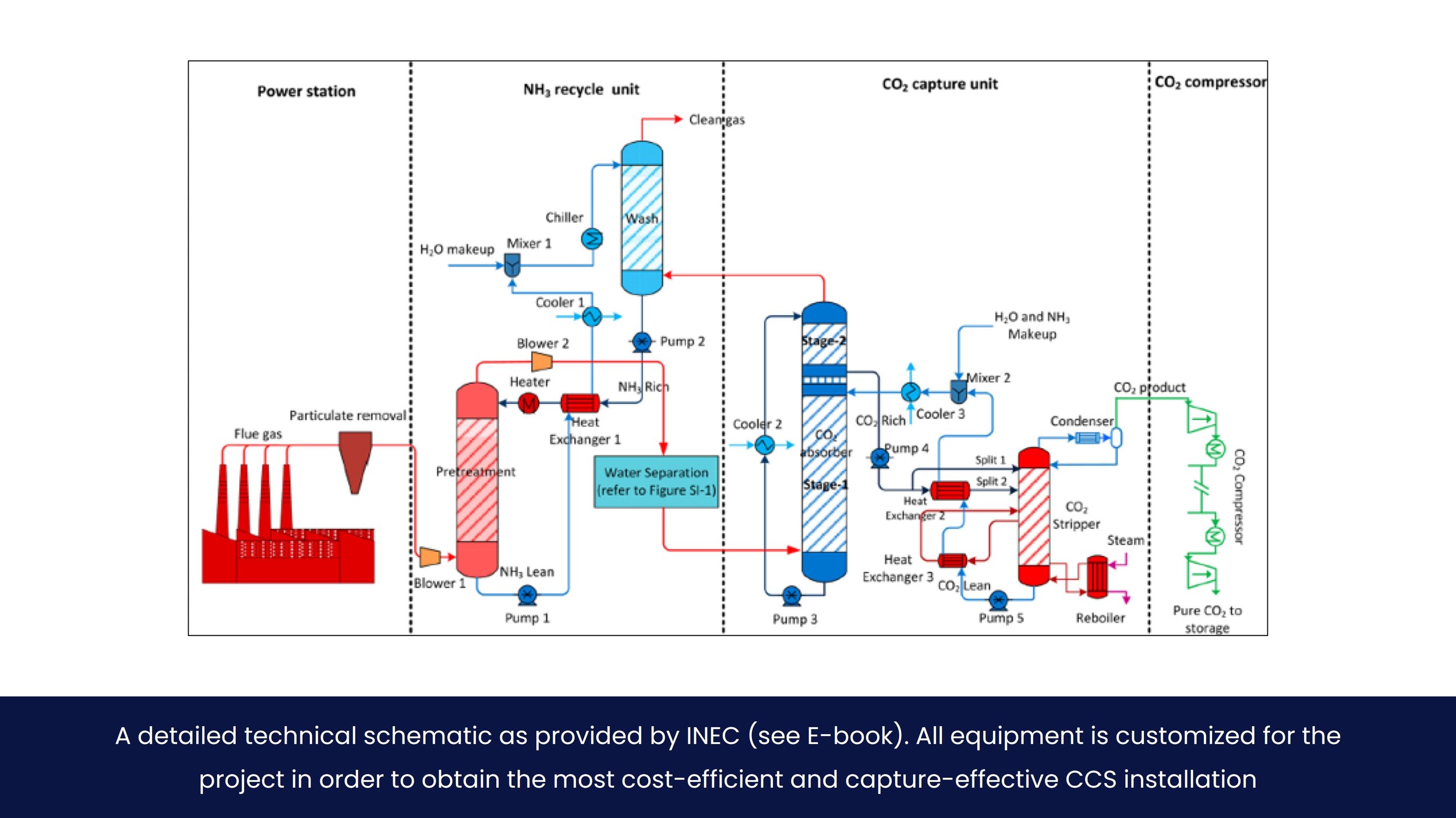
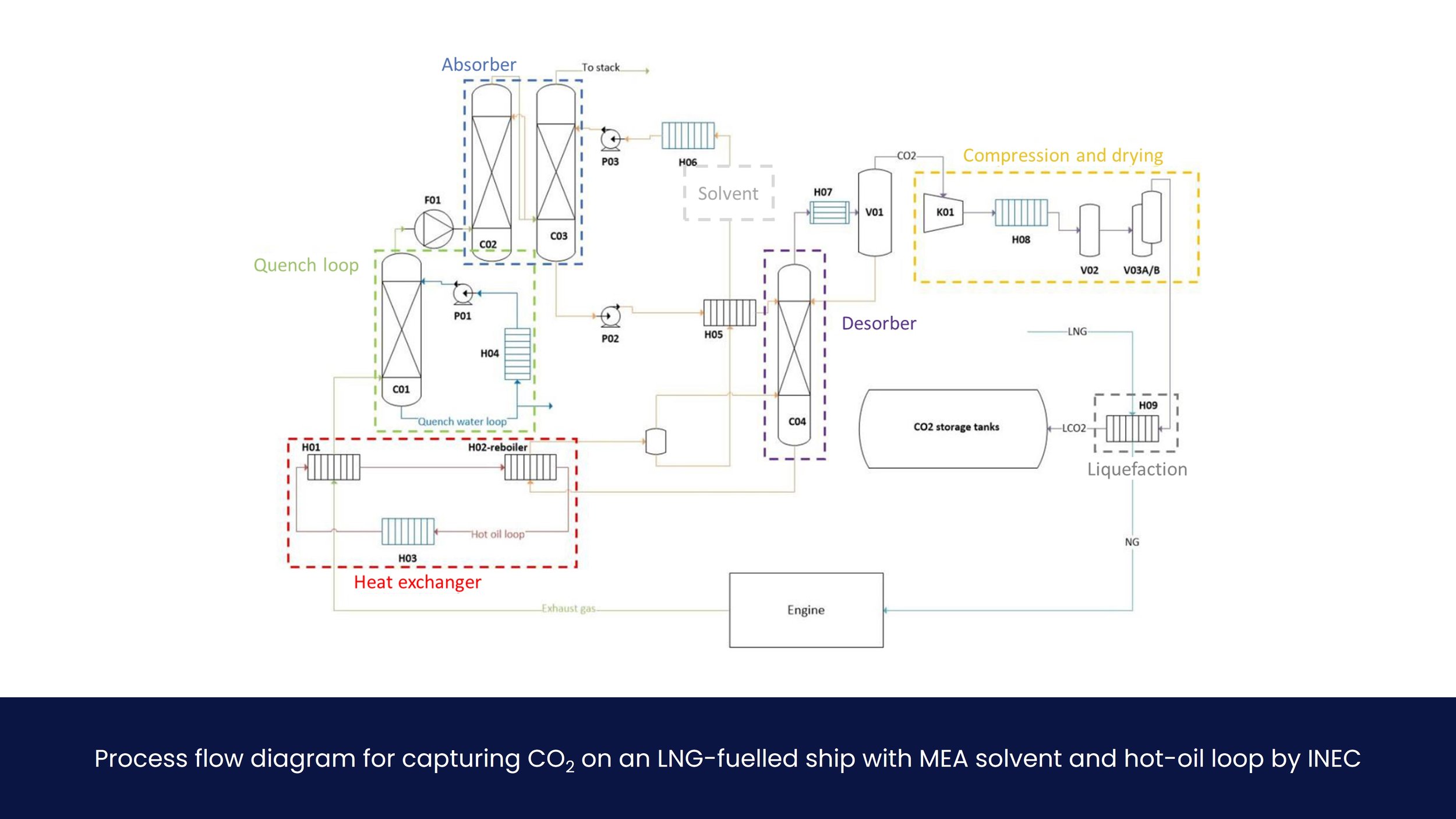
Carbon Capture and Storage (CCS) is considered a relatively simple chemical process on land. CO2 is separated from exhaust gas in the ‘absorber column’ by means of a ‘solvent’ to which the CO2 bonds. After CO2 bonds with the solvent, the solution is called ‘CO2-rich solvent’. It is transported to a ‘desorber column’, sometimes called a stripper. In this column the CO2 is removed from the CO2-rich solvent by adding heat, most commonly steam. What remains is ‘lean solvent’, plus a mix of CO2 and water vapour. The lean solvent is reused in the absorber column, the water vapour is separated from the CO2 before it is compressed and stored.
-
OCAP and Porthos - Rotterdam
OCAP (Organic CO¬2 for Assimilation by Plants) is a CO2 distribution network in the West of the Netherlands, used to transport CO2 capture from industrial processes in the Rotterdam port area to greenhouses throughout the Netherlands.
OCAP is a good example of carbon utilization, as there is already a well-established market with CO2 prices of €50 to €100 per ton. This could provide clear incentives for shipowners, as the reported costs for ship-based carbon capture and storage are close to these prices of CO2 (see chapter 5.0). Utilization would unfortunately diminish the reduction of CO¬2 in the atmosphere, so that would be a trade-off that has to be made.
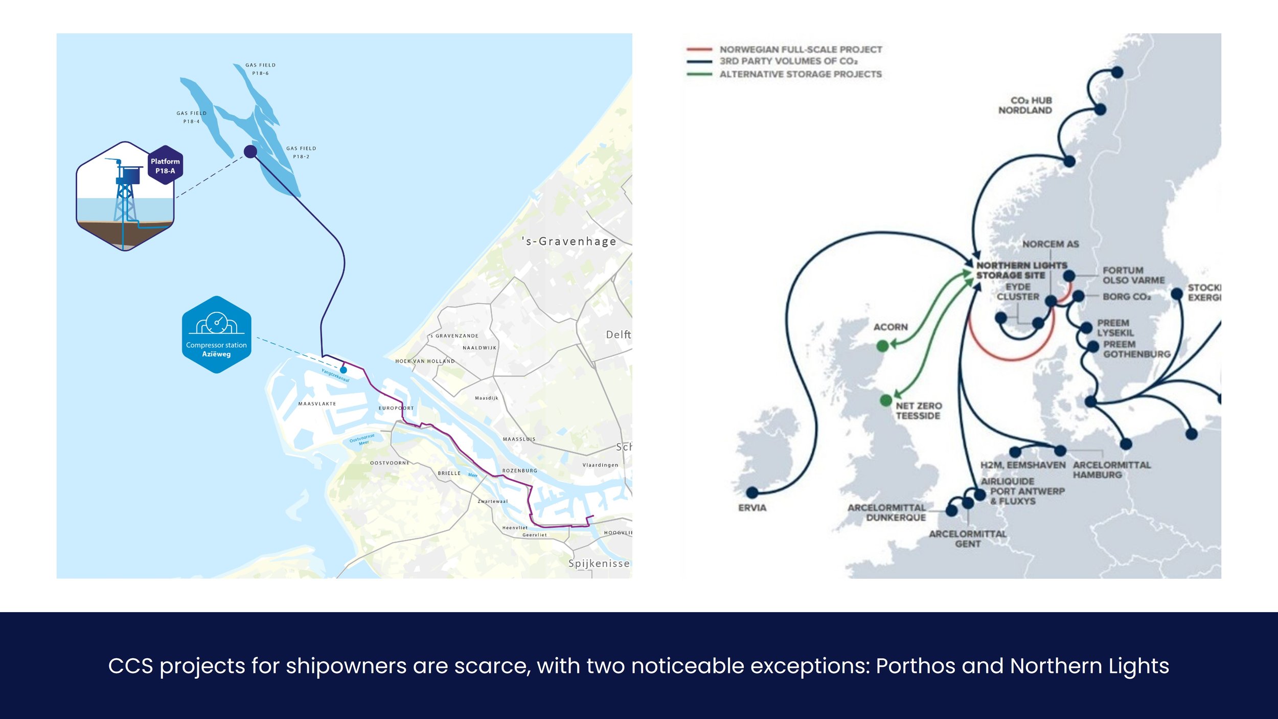
The network already covers an area of ~30 km but there are plans for expansion in order to accommodate additional CO¬2 shipped in from locations outside of Rotterdam, similar to the Northern Lights project. This project is called Porthos – Port of Rotterdam CO2 Transport Hub and Offshore Storage, with the clear aim to provide a ‘carbon sink’ for the industrial complex in the Rotterdam Area.
Northern Lights
Following a historic vote in parliament on December 15th 2020, Norwegian government announced its funding decision for the ‘Northern Lights’ CO2 transport and storage project. In cooperation with Shell and Total, the project aims to create a carbon capture and storage hub (or ‘sink’) in Norway, open to third parties. It will be the first ever cross-border, open-source CO2 transport and storage infrastructure network and offers European industrial emitters the opportunity to store their CO2 safely and permanently underground. A deal for the construction of the facilities has been struck between Equinor, Subsea 7 Norway and Aibel, paving the way for the facilities to be operational in 2024.
Northern Lights will be include accessible infrastructure for any third party to enable transport of CO2 from industrial sites to a terminal in Øygarden, from where it is transported by pipeline for permanent storage in a reservoir 2600 meters under the seabed. Northern Lights includes capacity to store up to 1.5 million tonnes of CO2 per year initially. Plans exist to increase the capacity to 5 million tonnes per year. Equinor, Shell and Total made a conditional investment decision on Northern Lights in May 2020. The project partners are now in the process of establishing a Joint Venture - subject to merger clearance.
Ship-Based Carbon Capture (SBCC)
The basics of ship-based carbon capture are similar to land-based processes. The largest difference is the available heat from exhaust gasses, which can be used to improve the process. In other words, CO2 from the exhaust is captured in a post-combustion capture process, which can be applied to virtually all ships sailing and for all fuels (e.g. HFO, diesel, LNG etc.). The captured CO2 is subsequently liquefied and temporarily stored on board, after which it needs to be offloaded either in port or via dedicated offloading vessels.
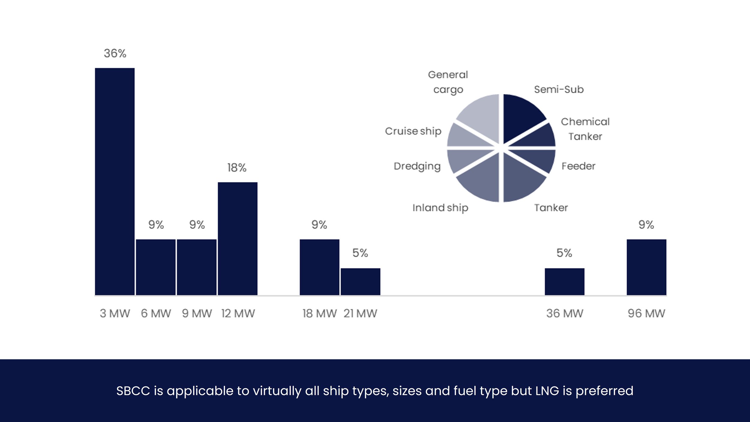
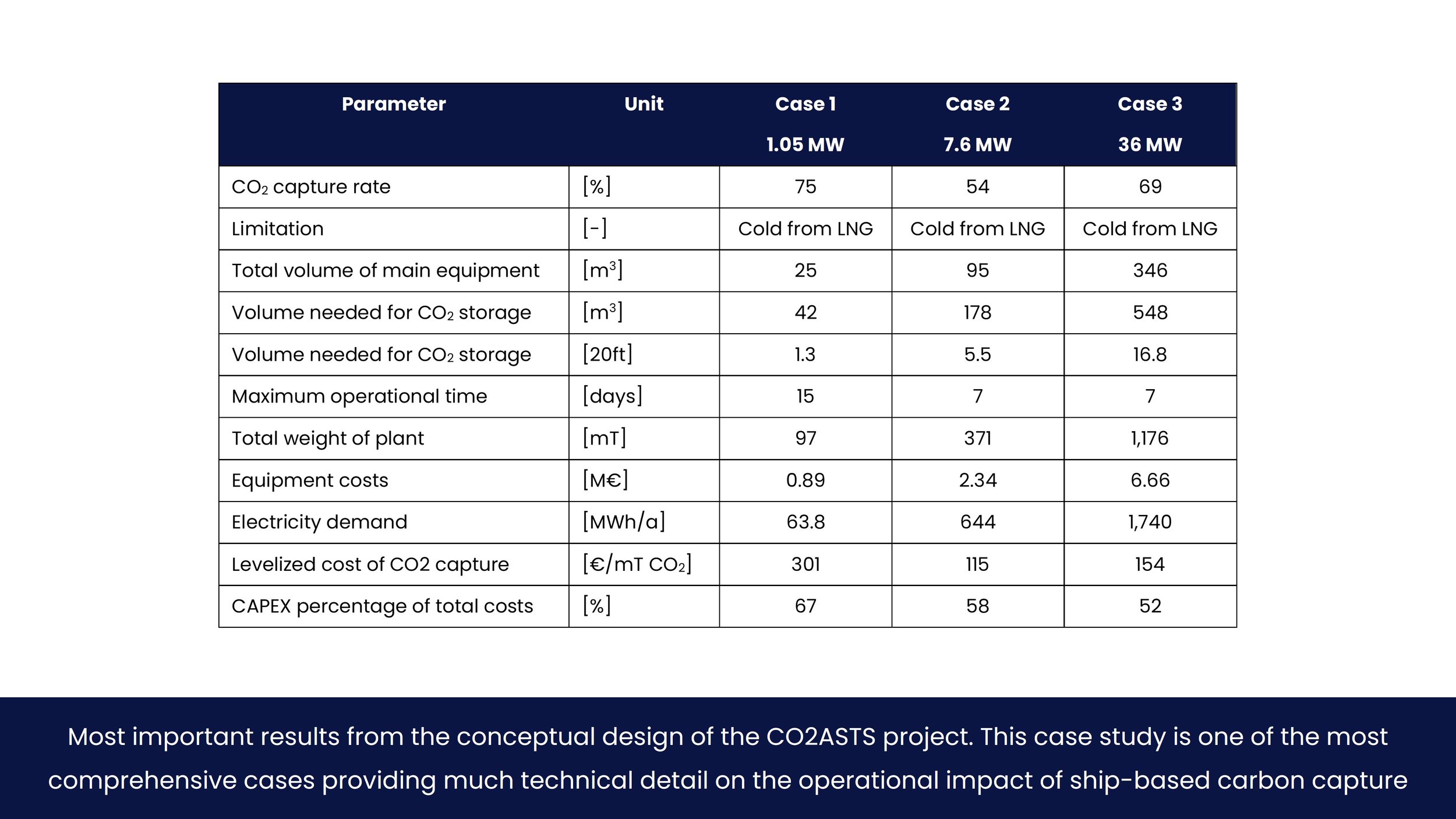
There is a good distribution of all kinds of different ship types, leading to the conclusion that ship type is neither a pre-requisite nor distinguishing factor in SBCC. There is a preference for LNG-fuelled vessels however, as the ‘cold’ from the LNG, coupled with generally higher exhaust temperatures, leads to improved efficiency of the heat exchanger and thus reduced cost.
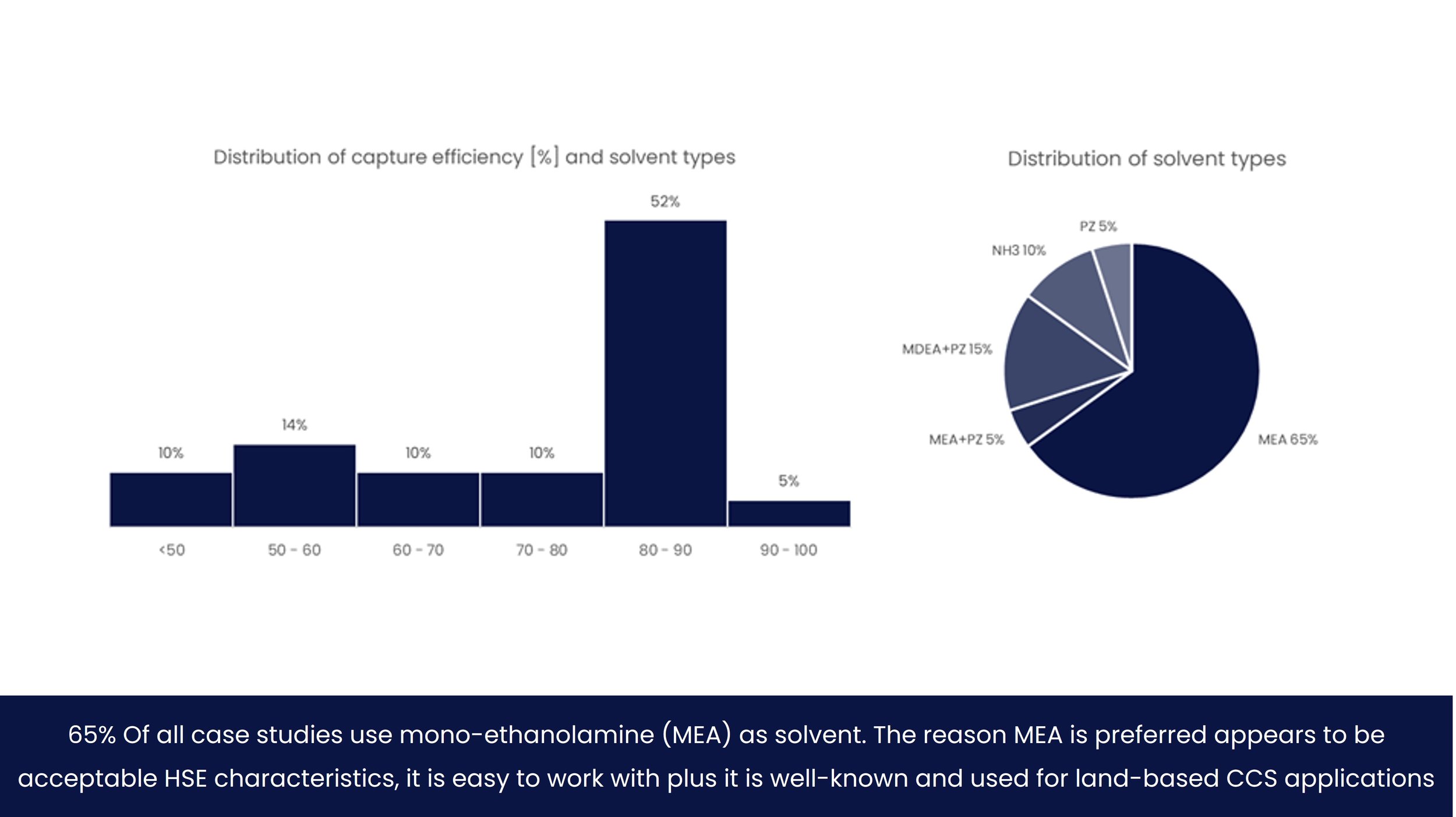
Generally speaking, capture efficiency of CO2 can reach up to 90%, but depends on engine type, settings and available heat in the exhaust gas. More than 50% of all cases have a capture efficiency of 80-90%, which appears to be a good estimate of what can be achieved.
-
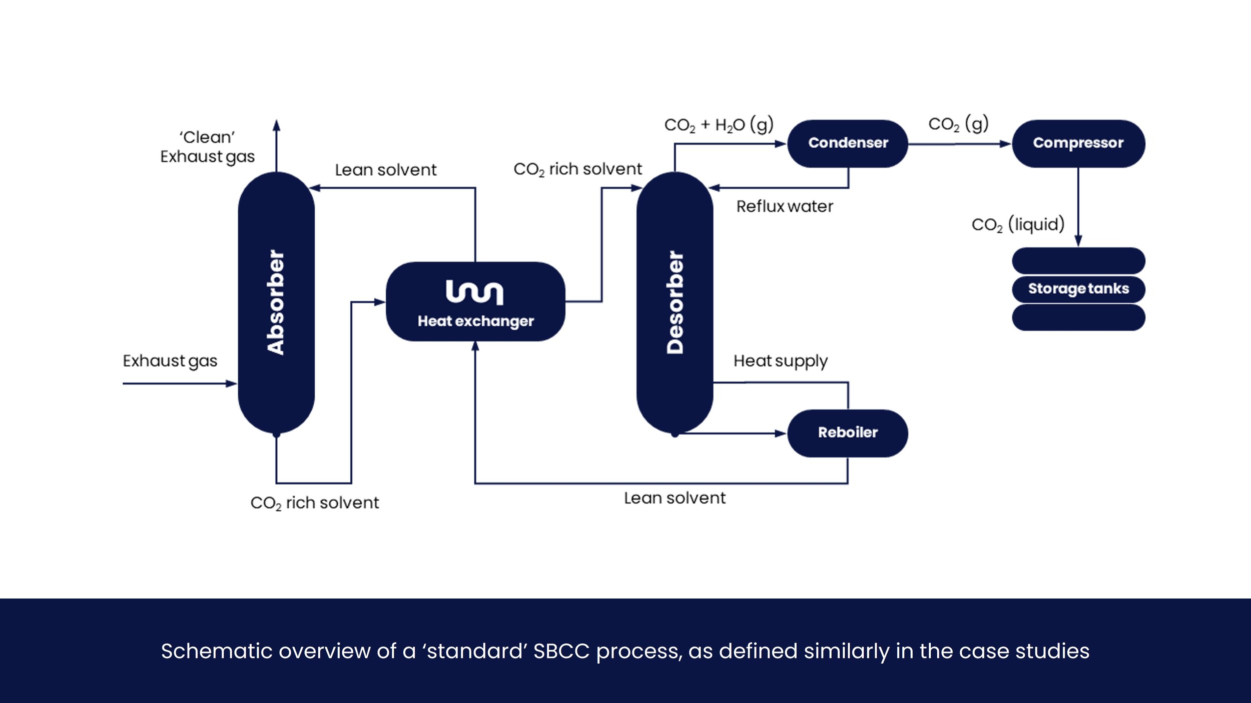
The chemical process of SBCC is similar to land-based carbon capture and storage. CO2 is separated from exhaust gas by means of a ‘solvent’ to which the CO2 bonds in the absorbed. After the CO2 is bonded with the solvent, this CO2-rich solvent is transported to the desorber. The CO2 is removed from the CO2-rich solvent by adding heat. This is where the biggest difference occurs from land-based solutions.
In most case studies a heat exchanger, supported by a reboiler, uses the heat from the exhaust gas to strip the CO2 from the solvent. This is done in order to reduce cost. After the CO2 is separated from the solvent, the lean solvent is reused in the absorber column, and the CO2 needs to be dried before it is stored. A more detailed description with more in-depth analyses on the equipment is elaborated upon in the subsequent section.
-
The absorber is a tall column through which the hot exhaust gas flows up. A shower-like spray installation releases a cold and ‘lean’ solvent into the column. The solvent ‘sticks’ to the CO2 and captures it from the exhaust gas. The CO2-rich solvent mix is collected at the bottom of the column. On the top of the column, ‘clean’ exhaust gas consisting mostly of water vapor is released into the atmosphere.
-
When heat is added to the CO2 rich solvent, the CO2 is released and the solvent becomes ‘lean’ again. This solvent fed back into the top of the absorber column via the heat exchanger in the next step.
At the top of the desorption column, a CO2 mixture rich with water vapour is obtained. This mixture is cooled, condensing the water, resulting in a 95-99 vol% pure stream of CO2, dependent on the pressure in the desorber and the temperature in the condenser. The CO2 is still in gaseous phase.
-
The exhaust gas coming from the engine offers unused high quality heat, which can be extracted and used for the CO2 desorption process. This can be considered ‘free heat’, as opposed to land-based operations.
This heat can be recovered from the exhaust gas by installing a waste heat recovery unit (WHRU) in the exhaust gas that transfers the heat of the exhaust gas to a heat transfer fluid. This heat transfer fluid can be used to supply the necessary heat to the capture plant, i.e. the desorption section.
The transfer can be a hot oil or steam, pending user preferences. In retrofit applications where a steam cycle is already present onboard, it makes sense to use part of the steam cycle. In retrofit applications where no steam cycle is in place, a different heat transfer fluid should be considered as it could decrease the footprint of the plant compared to a steam cycle.
-
The last step would be to liquefy and store the CO2. The liquefaction in Figure 7 is performed by a heat exchanger between the evaporating LNG and the CO2 product (in H09). Further heat integration can be performed between the gaseous CO2 product and the LNG that needs to be vaporized prior to injection in the engine. Since the LNG is stored at approximately -160 ◦C and 2 bar, this can be used to liquefy the CO2 product at pressures between the triple point (5.18 bar) and the critical point (73.8 bar).
The evaporation heat and the low temperature of the LNG will liquefy the CO2 product, which is then ready for storage onboard. The size of the storage tanks is dependent on the maximum time that the vessel is at sea before reaching a port where the CO2 can be offloaded and further sequestered. More about onboard storage tank sizes is discussed in section 3.1.
As can be seen in the phase diagram in Figure 10, the pressure and temperature at which this liquefaction step happens can differ, depending on the application. At atmospheric temperatures, at a pressure of 70 to 80 bar the CO2 is in supercritical phase, typically used for storage applications. Liquefaction at colder temperatures and lower pressures is usually considered for transportation purposes. From case studies, common temperatures and pressures for onboard storage are -50 to -20 °C and 2 to 20 bar.
Liquefaction and subsequent storage of CO2 in the supercritical condition is recommended to reduce storage space, but is a trade-off between operational restrictions and cost. From this perspective, LNG is the preferred fuel for ship-based carbon capture, as the cold from LNG can be used for liquefaction.
-
The solvent is a crucial aspect in carbon capture and the basis for many design choices – and restrictions – one of them being the capture rate of the installation. The below statements are a summary of all considered case studies, elaborated upon in the subsequent sections.
A solvent is a solution of an ‘amine’, the active ingredient that bonds with the CO2, and water. Both the amine itself, as well as the weight-ratio of amine and water determine the effectiveness of the solvent when absorbing CO2.
Most case studies consider ‘single amine systems’ only, as this approach allows to distinguish the fundamental differences between the different solvents. Land-based CCS facilities commonly use MEA, hence it is the historic staple choice for many ship-based applications as well.
65% Of all case studies use mono-ethanolamine (MEA) as solvent. The reason MEA is preferred appears to be acceptable HSE characteristics, it is easy to work with plus it is well-known and used for land-based CCS applications thus a mature technology.
Only MEA, piperazine (PZ), and aqueous ammonia (NH3), as well as blends of MEA-PZ and MDEA-PZ have been considered in the case studies. All solvents can reported to 90% capture efficiency on an individual basis.
The advantages and disadvantages of the different solvents as described in literature are from a generic perspective, i.e. not taking into consideration ship-based application.
Operational impact
Case studies indicate an average production of 2 m3 CO2 per day per MW. This can be used to calculate onboard storage space requirements and offloading time by multiplying the amount of operational days by 2 per MW. Storage of CO2 onboard can be done via fixed tanks, containers or a hybrid solution, pending on the operational profile and frequency of port calls of the ship. Case studies indicate a preference to store CO2 at 15 bar and -50 °C, in supercritical phase. At higher pressures, the CAPEX of the storage tanks increases, while at lower pressures the liquefaction system becomes more expensive.
-
Table 2 shows that for quick reference, the minimum required storage space would be 0.79 m3 per installed MW per day, and the maximum would be 3.18. The average CO2 production is approximately 2 m3 per installed MW per day.
The most important aspect for a shipowner is arguably the storage space available. Cases studies that provide storage capacity range between 15 to 23 m3 required per MW installed with one outlier suggesting 42 m3 for a 1 MW vessel (the smallest investigated). A generalized value of 20 m3 per MW installed for CO2 storage space required can be adhered when this outlier is neglected.
These vessels would then be able to operate with for 7 to 29 days before needing to offload. Total proposed amount of CO2 storage space on these ships ranges between 42 m3 for the smallest vessel to 2,200 m3 ¬for the largest.
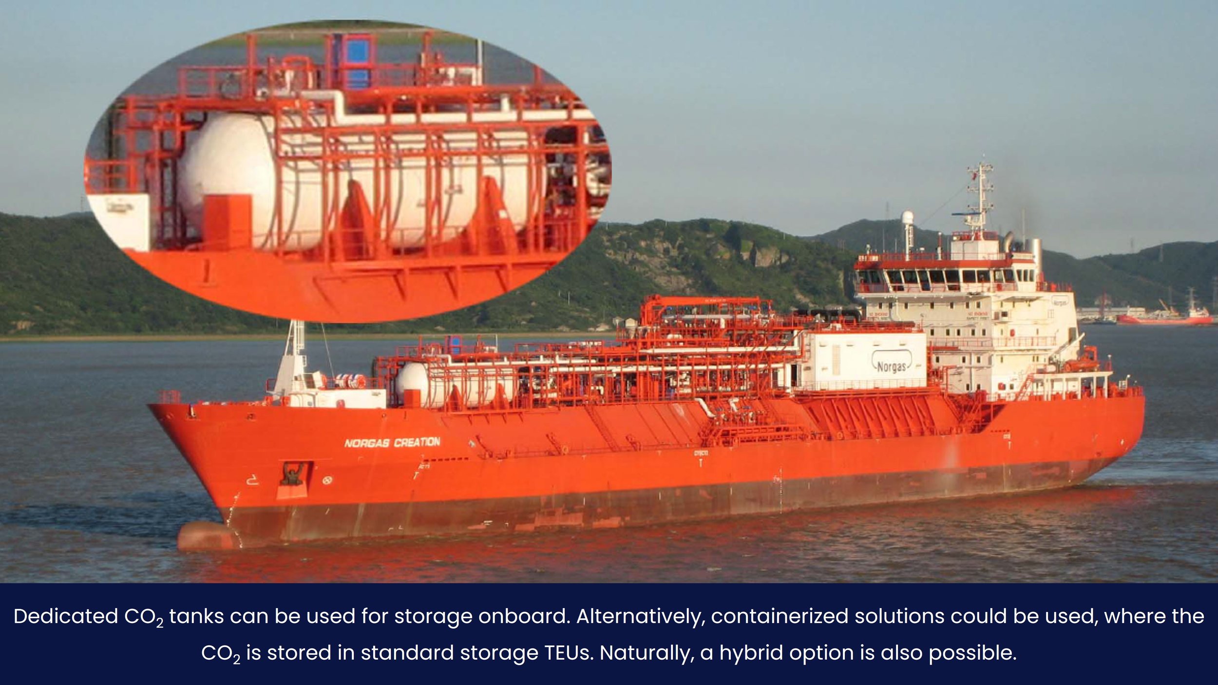
CO2 can be stored as a liquid in tanks. Broadly speaking, three options are available for storage: fixed onboard tanks, swappable containers or a hybrid solution. All options are technically feasible, and depend on a shipowner’s preference and operational profile. More information on storage can be found in section 4.1.
-
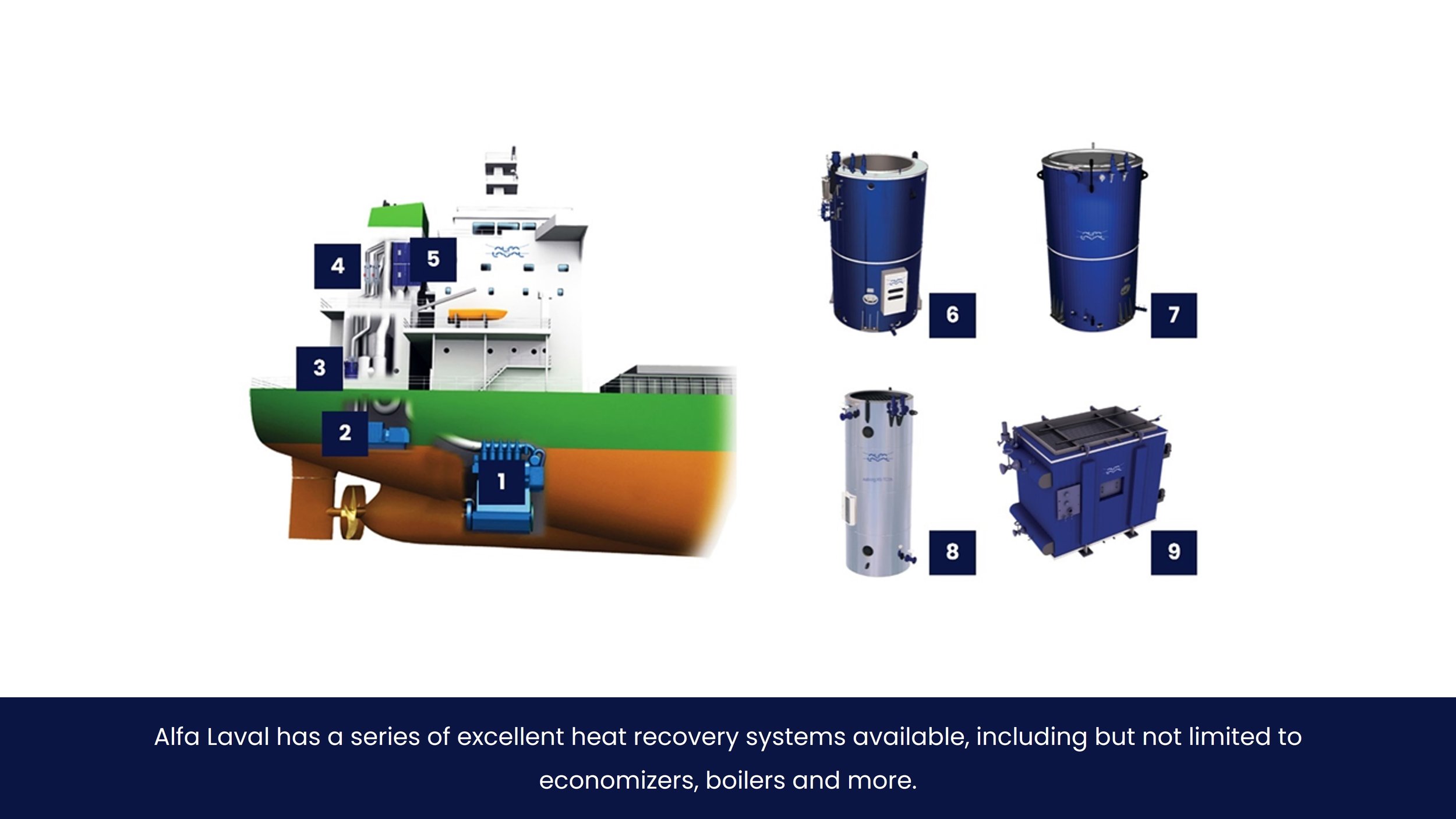
The most obvious choice to accommodate the heat required for ship-based carbon capture is to use a Waste Heat Recovery Unit (WHRU).
There are two commonly used heat recovery devices used in the maritime industry, the Exhaust Gas Boiler (EGB) and Exhaust Gas Economizer (EGE). The availability of these systems, plus the fact that they are often required to operate the ship from an economic view, make them commonplace in the marine industry.
The transfer can be a hot oil or steam, pending user preferences. In retrofit applications where a steam cycle is already present onboard, it makes sense to use part of the steam cycle. In retrofit applications where no steam cycle is in place, a different heat transfer fluid should be considered as it could decrease the footprint of the plant compared to a steam cycle.
Impact when refit is required to accommodate heat exchanger and piping is significant and would require a (dry-)dock in most cases. Estimated CAPEX costs for heat exchangers are €100 per kW.
-
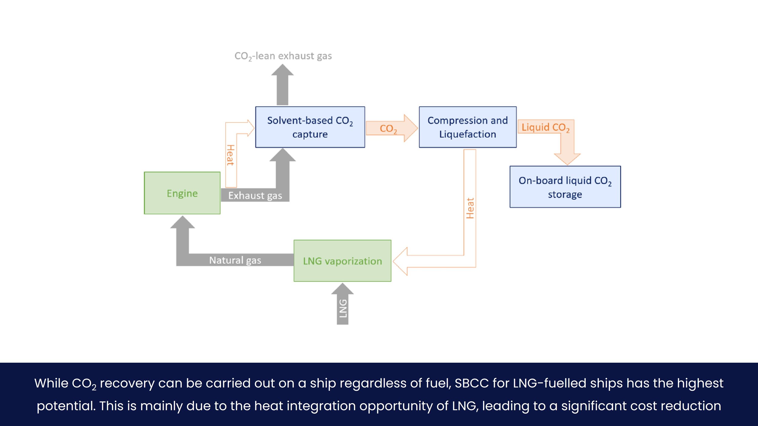
While CO2 recovery can be carried out on a ship regardless of fuel, SBCC for LNG-fuelled has the highest potential. This is due to the relatively clean exhaust gas to be treated, and the heat integration opportunity between the LNG and the CO2 product, both leading to a significant cost reduction.
LNG
Because of the high temperature of the exhaust gas (typically ca. 350-400 °C), heat can be used for the desorption part of the CO2 capture process, greatly reducing OPEX of the process. Secondly, the evaporation heat of LNG can be used to cool and liquefy the CO¬2, thereby reducing the required liquefaction pressure. Since the LNG is stored at approximately -160 °C and 2 bar, it can be used to liquefy the CO2 product at pressures between 7 and 20 bar and -50 °C and -20 °C respectively. The former aspect removes the requirement for a heat source for CO2 recovery, while the latter reduces the cost of compressors, thereby significantly reducing the total cost of CO2 recovery.
In addition to heat integration and thus cost reduction potential, LNG has a much lower sulphur content (<0.004 wt%) resulting in cleaner exhaust gas as a result. In practical terms, that means that the waste heat recovery unit can recover heat from the exhaust gas to below 180 °C, which is the acid dew point. Below this temperature, sulphur species and salts may arise that can interfere with the absorption process. Since LNG has a very low sulphur content, this limit is not relevant anymore. the flue gas temperature can be decreased to approximately 135 °C (considering that the energy needs to be transferred through the heat transfer fluid). This maximizes the amount of heat that is available for the CO2 capture plant.
HFO and Diesel
On vessels using Heavy Fuel Oil (HFO) or marine diesel as a fuel, a waste heat recovery unit can recover heat from the exhaust gas to ca. 180 °C, since care has to be taken not to cross the acid dew point, as these type of fuels can contain a large concentration on sulphur species (ca. 0.5 up to 3.5 wt%).
With a high concentration of sulphur species in the exhaust gas, there is a chance that the solvent is consumed by SOX species, creating heat stable salts (HSS) that could accumulate and interfere with the SBCC process. To mitigate this potential issue, a base (e.g. NaOH) can be added to the quench loop to absorb the SOX species.
As a consequence of the heat recovery limitations, HFO and diesel would either have lower capture efficiencies, or require additional fuel consumption to ensure high capture rates (see 2.3.3).
-
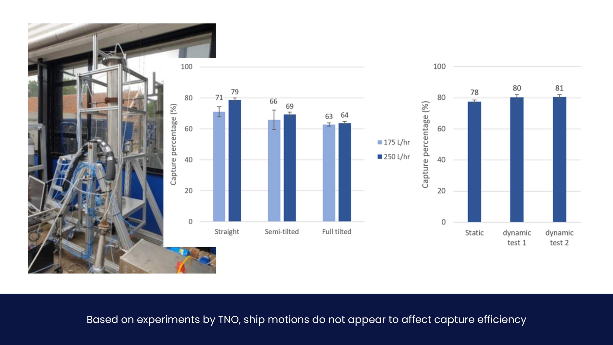
A key difference between land-based and ship-based carbon capture are motions of the vessel, and thus physical movement of the entire capture plant. Experience on how pitch, roll, heave and other motions affect equipment and capture efficiency is limited. TNO investigated this for the DerisCO2 project by means of an experimental tilting table set-up. Based on these results it is expected that vessel tilting at sea will have no negative effect on CO2 absorption . In fact, an increase in efficiency might arise due to ‘mixing’ of solvent and exhaust gasses.
-
The case studies show no preference of ship-based carbon capture for a specific type or size. Storage availability, fuel selection and operational profile are far more important, in particular the ability for offloading close to shore or regularly in port. While CO2 recovery can be carried out on a ship regardless of fuel, LNG-powered ships are preferred (see section 3.3). It might also be argued that (chemical) tankers equipped with thermal equipment and compressors have some advantage, but this can only be considered on a case by case basis.
Operational profile
Ships sailing from port to port have a clear advantage, as their operational profiles and destinations can be considered ‘constant’, resulting in a relatively easy-to-predict CO2 production per trip. This helps in dimensioning the carbon capture installation on board. Ships sailing to the same port also have the advantage of simplified offloading logistics (see chapter 4.0). This advantage stems from the absence of uncertainty with regards to the stored CO¬2, which remains a crucial aspect for all ship types.
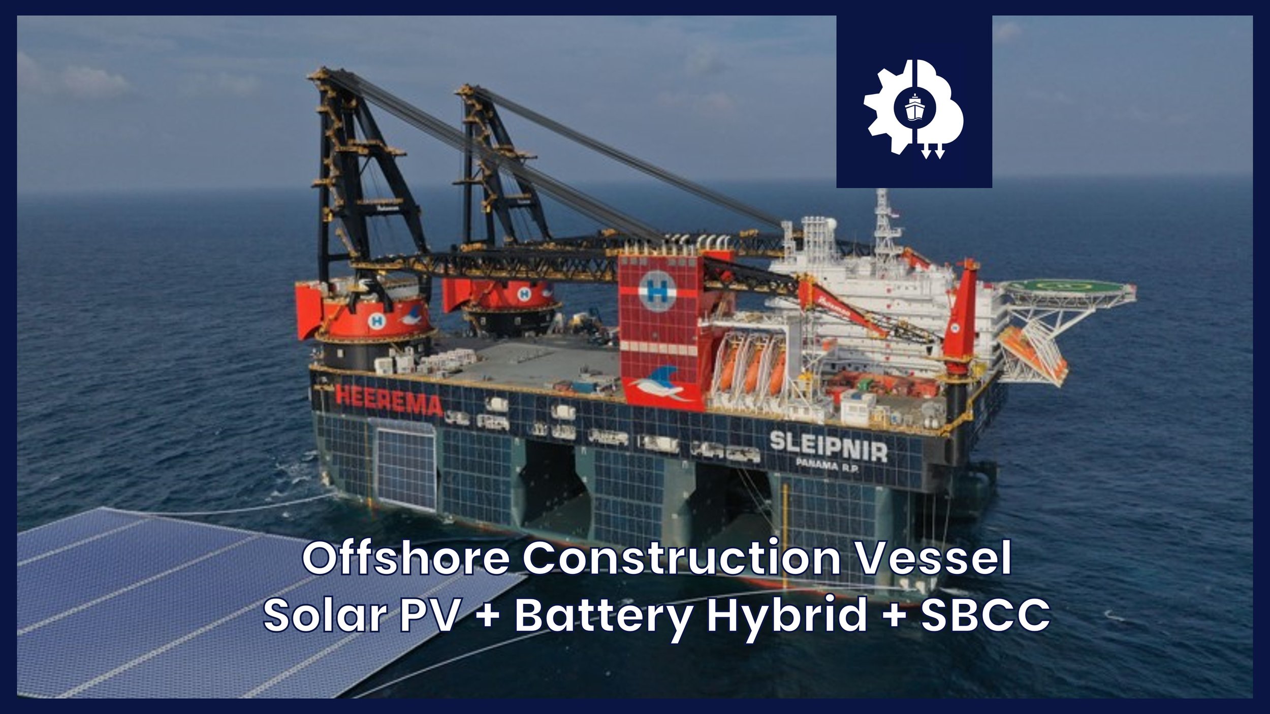
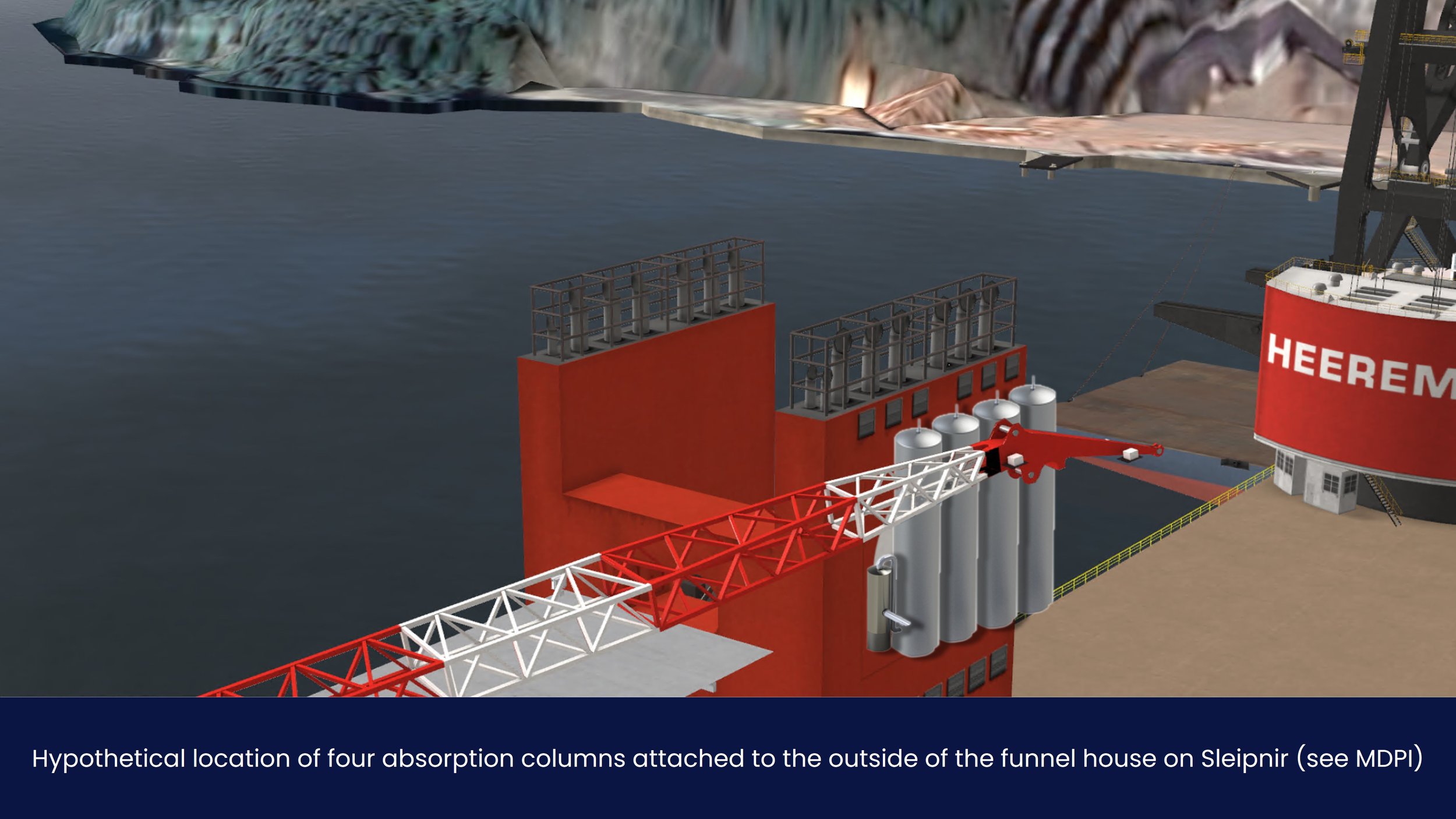
Disregarding this uncertainty, there remains an appeal of SBCC for ships that do not have regular port calls or ‘home ports’. Offshore construction vessels or other types of vessels that have a stochastic operational profile that is harder to predict, commonly have the advantage of space on board. These types of larger vessels can easily accommodate hundreds of not thousands of cubic meters of storage tanks in addition to capture installation equipment. In addition, these vessels are typically supplied by means of supply vessels on a regular basis, which could serve as a basis for offloading logistics (see chapter 4.2).
To summarize, whether regular port calls or offloading options arise due to supply vessels, regular offloading opportunities in general are most important.
Logistics
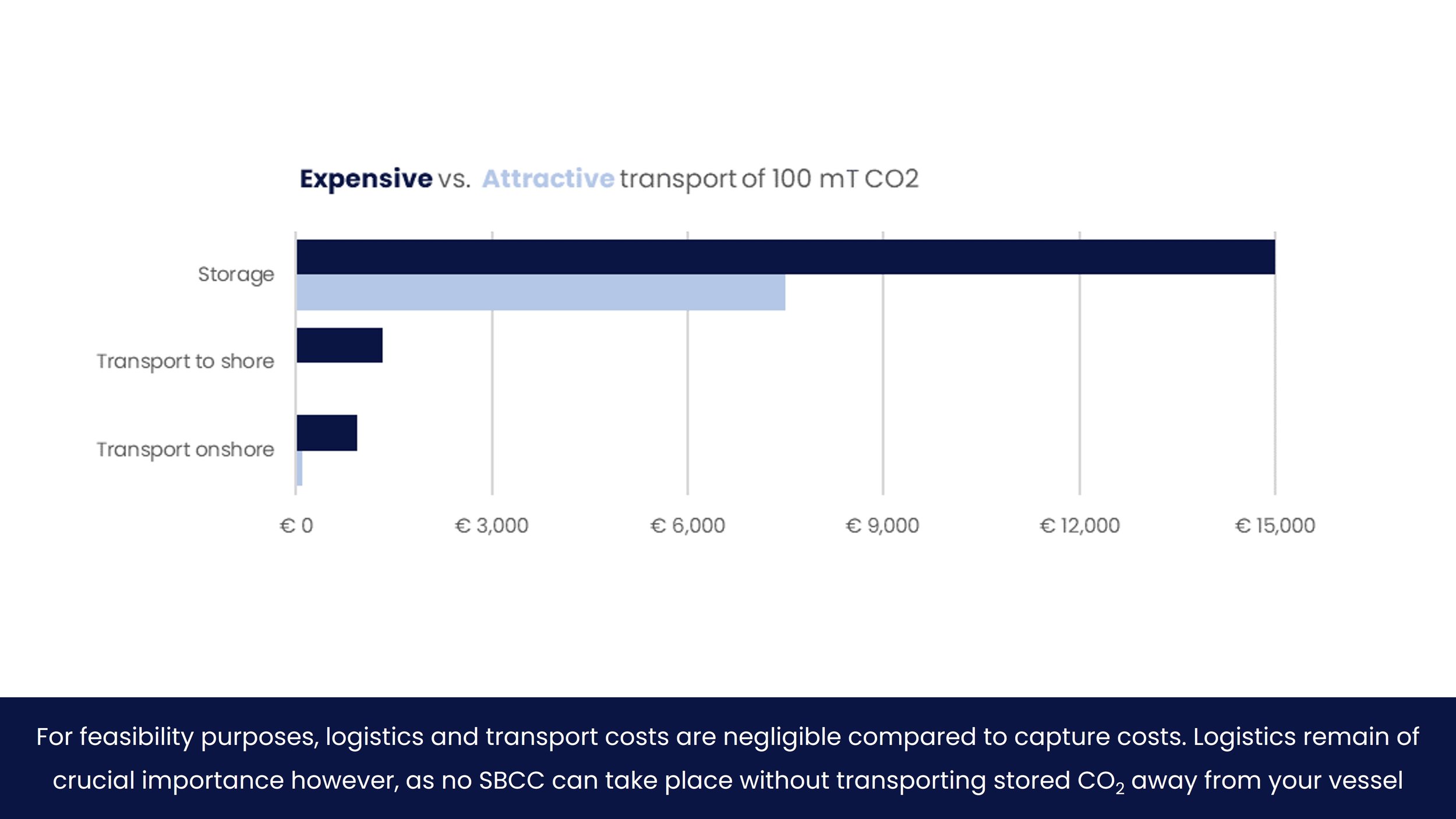
Ship-based carbon capture can be logically divided into four main steps: storage, transport to shore, transport onshore, and utilization onshore, where utilizations includes sequestration.
Permanent storage – also called ‘sequestration’ - ensures CO2 reduction is achieved. Utilizing CO2 for land-based applications has the benefit of potential revenue for the shipowner, but is always accompanied by CO2 emissions to the atmosphere.
For feasibility purposes, the costs for transport are negligible compared to the costs for capture. More information on logistics and transportation costs can be found in the E-book.
-
Storage of CO2 onboard can be generalized into three options: fixed tank, containers or a hybrid solution. Regardless of storage type, all case studies suggest a liquefaction pressure of 15 bars for optimal storage conditions, preferably in a supercritical state. At higher pressures, the CAPEX of the storage tanks increases, while at lower pressures the liquefaction system becomes more expensive.
Fixed tank
A fixed tank with large volume can be build or refitted onboard to store all CO2 produced. This could be accomplished with a single large tank, or in multiple smaller tanks. This options is a great solution for (large) dedicated ship types with regular visits to the same port, in particular LNG vessels or other liquid gas carrier types.
An advanced example for this type of solution is Høglund Marine Solutions & HB Hunte Engineering’s new ‘bilobe’ tank concept for LPG and CO2 transportation. It more than doubles the transportation capacity of liquid CO2 over current vessel capacity without the size, weight and stability concerns that would have come from a higher capacity “monolobe” design. The solution is readily available for use in existing tanker designs.
Containers
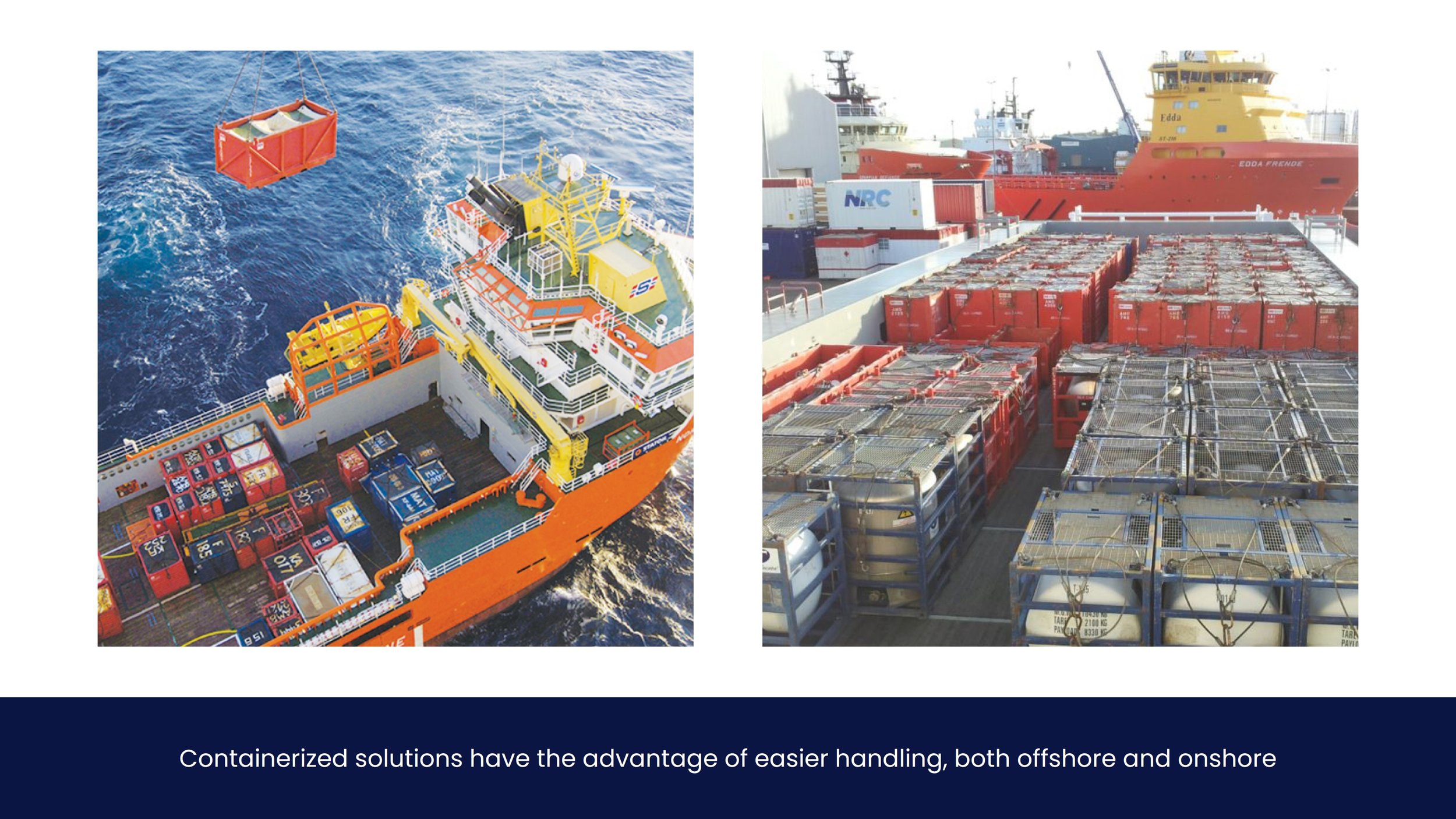
CO2 can be stored in standardized ISO containers with TEU dimensions of 10, 20 and 40ft, where a forty foot equivalent CO2 tank has a capacity of 53.3 m3. Transporting CO2 via containers is already a common practice worldwide. This solution is a great deal more flexible than fixed tanks and has the benefit of easy offloading. However, storage space is used less efficiently as each cylinder includes ‘empty space’ in the box-shape.
Hybrid
A hybrid option with both fixed tank(s) and containers onboard would provide the advantages and disadvantages of both solutions. It is only recommended when enough (deck) space is available. From a technical standpoint however, this could be very interesting as the fixed tank would provide the storage buffer for operations, and the containers would provide flexibility for on- and offloading anywhere without the need for dedicated offloading ships.
-
Once the storage is full, the recovered CO2 must be offloaded. Pending on the ship’s operational profile and port calls, this can be performed by the vessel itself while in port. This consideration is outside the scope of this section, as this will more or less be an operational limitation in terms of time (and opportunity cost of the ship). This section will focus on transporting CO2 from ship to shore using other vessels for CO2 transportation.
CO2 production rates and consequently offloading times are discussed in section 3.1. This section focuses on modal type of transportation only.
When a single or multiple fixed tanks are installed on the carbon capture vessel, offloading in port or a liquid gas carrier is preferred. When containers are used for onboard storage, a supply vessel or storage barge is preferred. It is technically feasible to create on- and offloading equipment from and to tanks or containers, but this is undesirable from an operational standpoint.
-
Onboard transport of the liquid CO2 can be performed in multiple modalities towards the end user, i.e. via existing pipeline such as the OCAP pipeline in Rotterdam, via road transport on trucks, via rail transport or via inland waterways vessels. A hybrid combination with multiple modes of transport can also be used of course.
Storage via containers would provide the benefit of flexibility. Containers can easily be transport via any modality around the world, except for pipeline, as is shown in Figure 25. To accommodate liquid CO2 in bulk, port terminals would either have to be connected to existing pipelines or storage facilities (Rotterdam or Norway) or transfer terminals from and to containers would have to be made. This would required additional processing and thus cost.
-
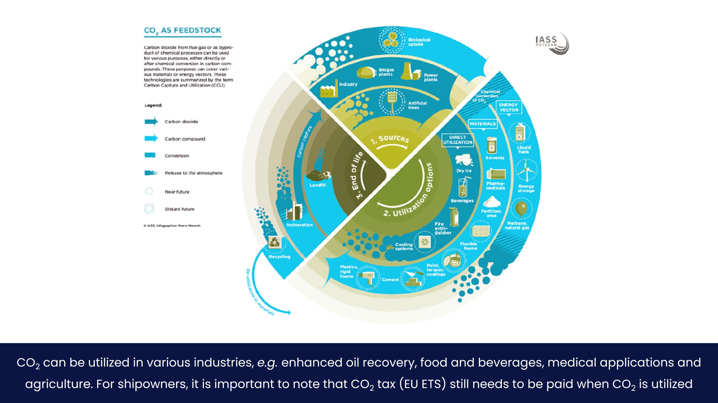
Utilization in the scope of this guide includes two main modes of ‘utilization’. The first mode is actual utilization by another user in the chemical, beverage of agricultural industry. For example, liquefied CO2 captured from LNG combustion can be of a very high (food) grade (>99%), which can be sold in excess of €100 per metric ton. The second mode is ‘sequestration’, or permanent underground storage. For this mode, it is becoming clear that no carbon taxes would have to be paid, thus also resulting in incentives in excess of €100 per metric ton.
A few examples of the CO2 life cycle, including utilization vs. sequestration, are shown in Figure 26. The three main utilization paths considered are direct utilization, as feedstock in materials processing and processing into energy sources. The main benefit of CO2 utilization, in the context of carbon capture, is that economic incentives are provided to something which was originally seen as a waste product.
The mode of utilization is a trade-off between emission minimization, costs and perhaps even client preferences. The different options for utilization and sequestration are elaborated upon in the subsequent sections.
Utilization
Utilization by another user has the benefit of providing a revenue stream for the shipowner. However, Utilizing CO2 is always accompanied by CO2 emissions to the atmosphere. It is therefore still subject to carbon tax, see 0. The three main utilization paths considered are direct utilization, as feedstock in materials processing and processing into energy sources. Some examples for each of these utilization paths are shown in the table below. These represent but a fraction of the available options and are shown merely for demonstrative purposes.
Utilization generates revenue by selling ‘your CO2’ to a user. The price for high-grade CO2 is in the order of €100 per mT at the time of writing.
Sequestration
Sequestration means storing the CO2 underground for an indefinite period of time, preferably forever. This practice involves pumping large amounts of CO2 into an empty oil or gas field. Reservoirs of this kind have been used for some time for CO2 storage and extensive experience has been gained in the oil and gas industry with enhanced oil recovery (EOR). The global underground storage capacity is estimated to be between 5,200 and 27,200 Gigatons. To illustrate: the largest crane vessel in the world produces about 50 megaton CO2 per year, which equates to 0.000001% of global storage. The availability of permanent storages are limited to non-existent however, with the Northern Lights project in Norway appearing to become the first commercially available ‘carbon sink’ for shipowners.
Permanent storage generates revenue by means of carbon tax avoided, see 5.4.1. The costs for EU ETS are in the order of €85 per mT at the time of writing.
Economics
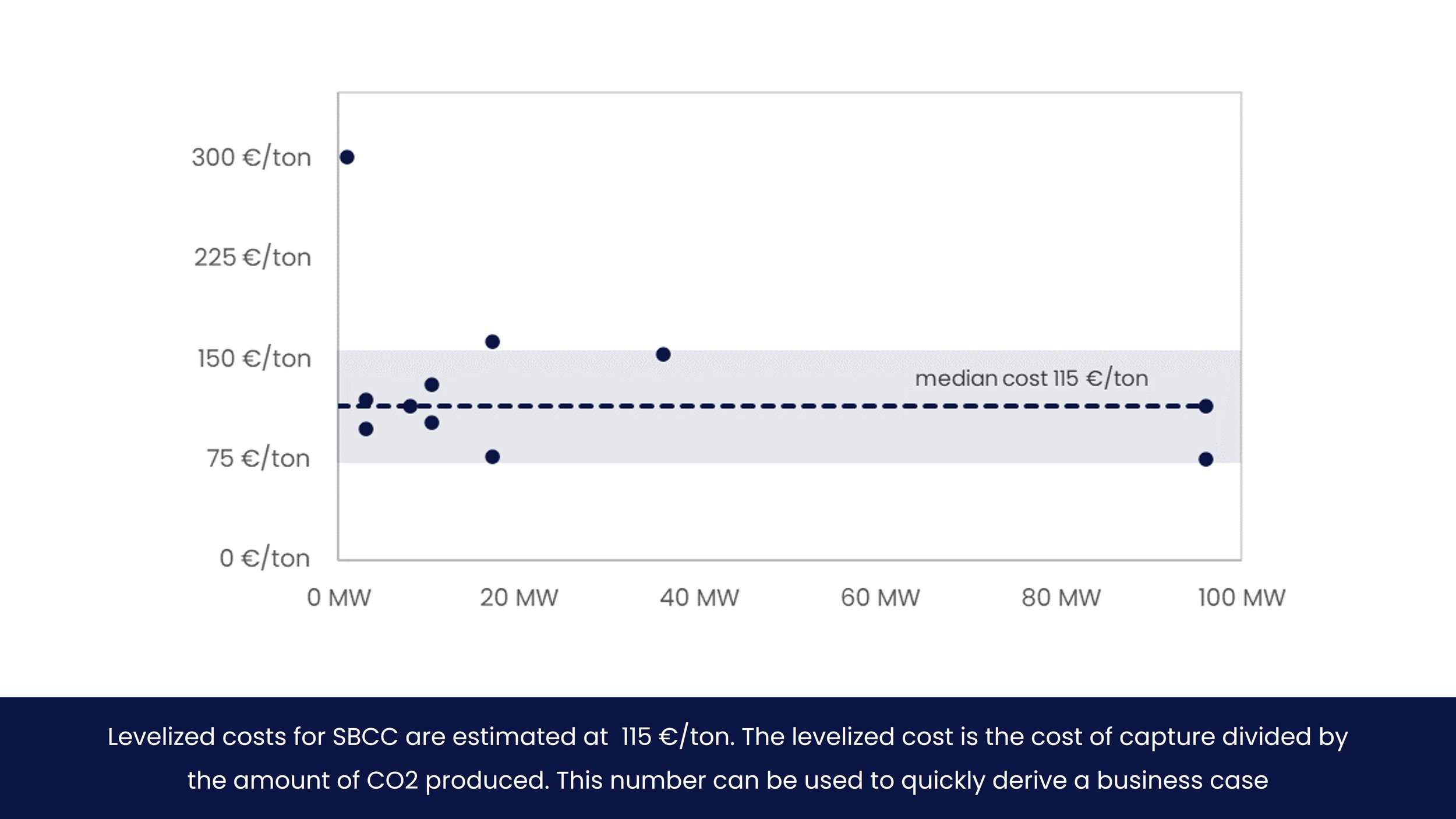
The median levelized costs of ship-based carbon capture for all case studies considered is €115 per mT. Approximately 80% of all case studies state a levelized cost of capture above €75 and below €150 per mT.
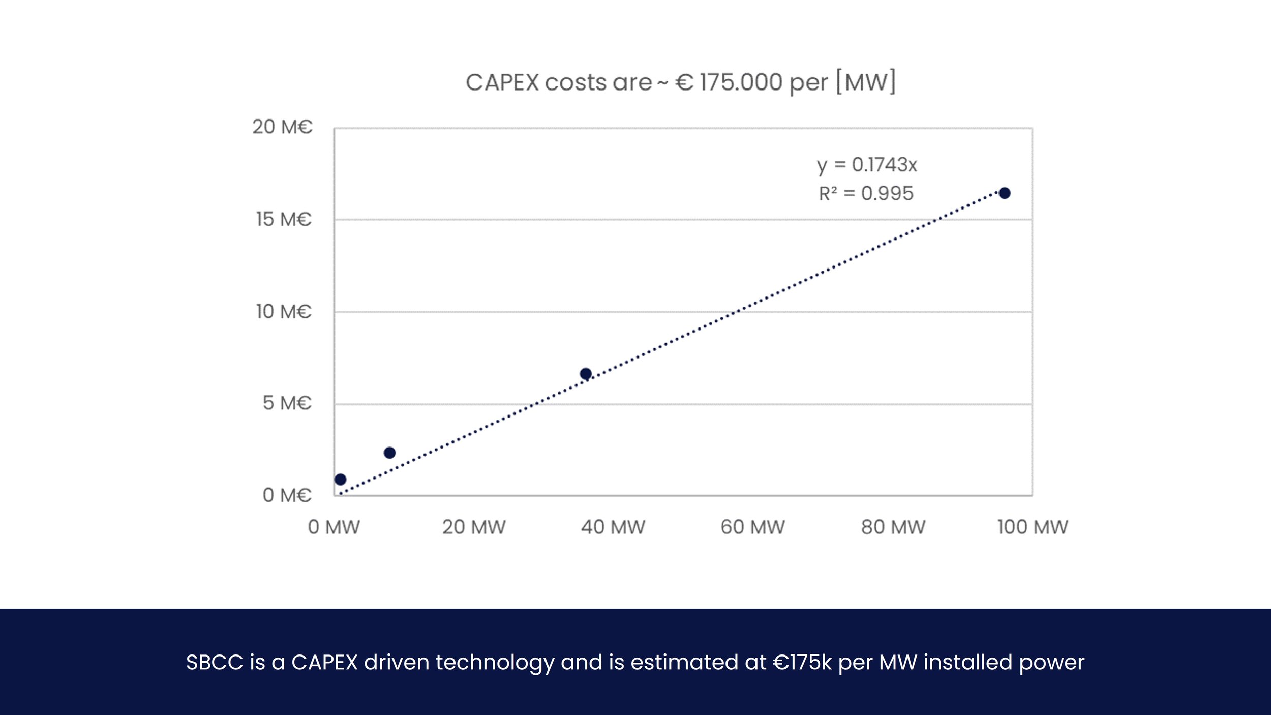
Ship-based carbon capture costs are CAPEX dominated, i.e. equipment and refitting costs required for the capture process. CAPEX costs are estimated at €175k per MW installed power[2].
By expressing the cost of ship-based carbon capture in € per mT, the payback time can be immediately derived. In practical terms; if the levelized costs of carbon capture plus the permanent sequestration costs are less than the carbon tax a shipowner needs to pay, there is a business case9.
More information on economics can be found in the E-book.
-
The costs for ship-based carbon capture are commonly expressed as levelized cost in euros (or dollars) per metric ton CO2. Unless stated otherwise, levelized costs for all case studies are calculated by dividing the total CO2 capture costs [€] with the amount of CO2 captured over the lifetime of the installation [mT] .
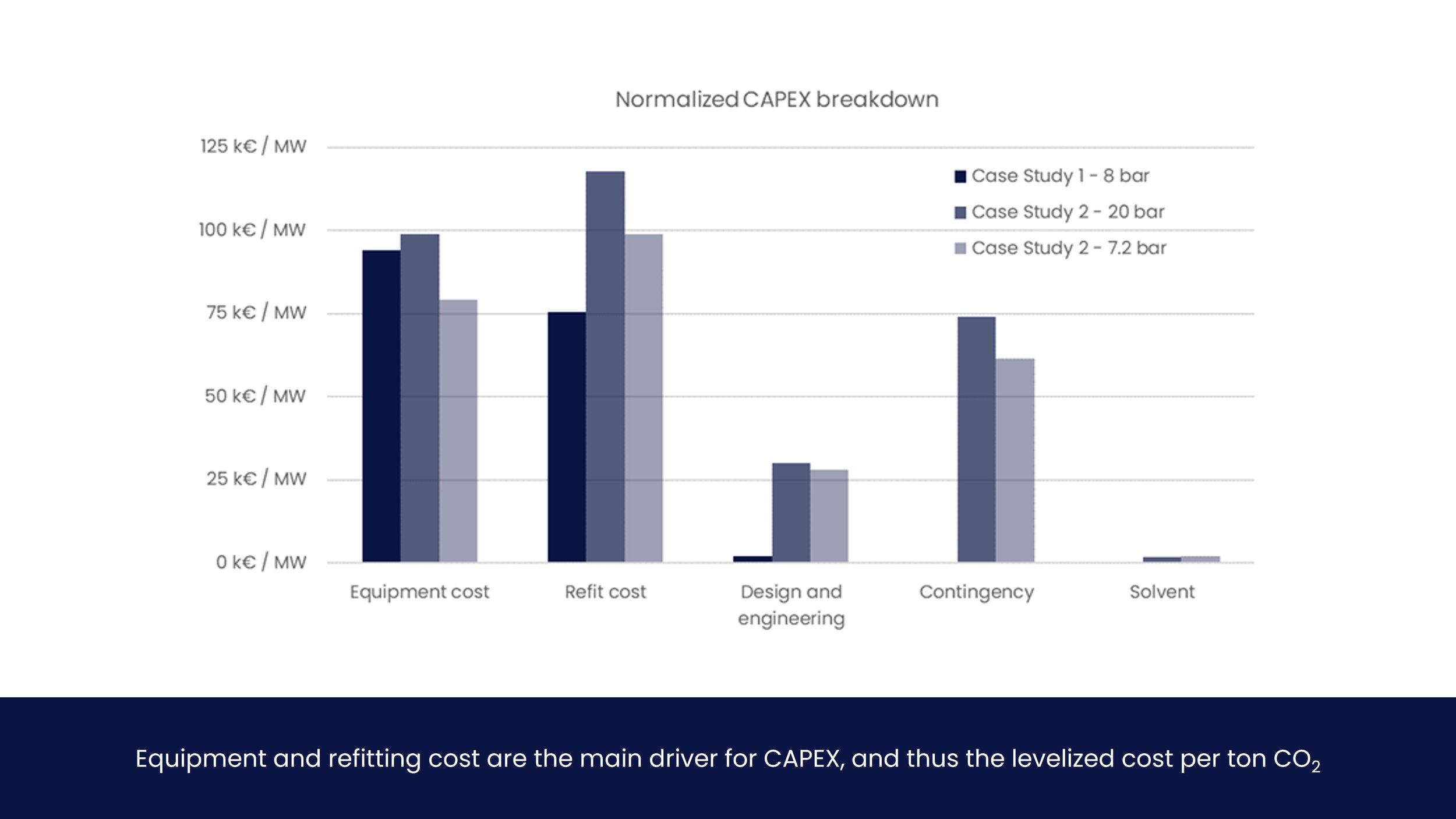
This approach provides easy cost comparison between different cases, components and supply chain phases, as specific costs can be expressed as a part of these levelized costs. For example, the costs of the columns and heat exchangers (generally the most expensive components) or the installation costs (which can be in the same order of magnitude as the equipment itself) could be expressed as a portion of the levelized costs. An example of a levelized cost breakdown is shown below.
In addition, a levelized cost approach instantly provides a basis for the break-even price of carbon tax for ship-based carbon capture to work from an economic perspective. When carbon tax is equal to levelized costs of capture plus permanent sequestration costs, there is a business case to be had.
-
Several case studies provide an economic breakdown of the CAPEX costs for carbon capture, in particular case studies 1 and 2 . Comparing these costs is difficult, due to the difference in assumptions and methodology. Nonetheless, a breakdown of levelized CO2 costs as well as CAPEX costs is provided in the below figures and tables, normalized where possible to allow for easier calculations.
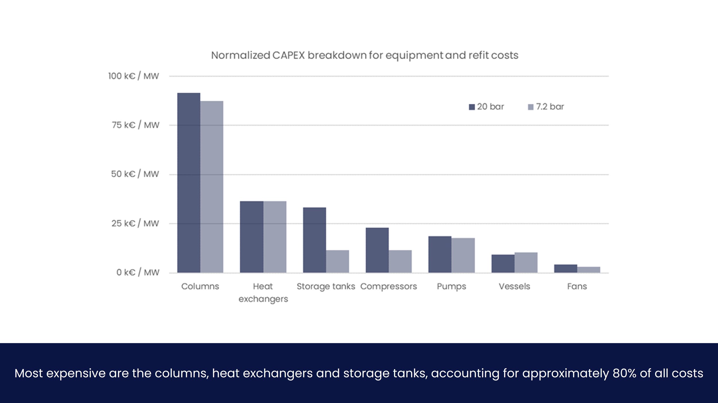
These analyses show that equipment cost are dominated by the columns and heat exchangers, accounting for 60 to 70% of all the equipment cost. Storage tanks and compressors account for 10 to 25% of equipment cost, increasing in cost with higher storage pressures.
Despite differing methodologies and assumptions used in case studies to derive costs, all case studies concur that ship-based carbon capture is a CAPEX dominated technology. The reason for this is elaborated in the subsequent section.
Why SBCC is CAPEX dominated
For large scale land-based CO2 capture processes, the OPEX costs are expected to be approximately twice the CAPEX costs. The OPEX costs are mainly determined by the steam demand to provide heat for the desorption of CO2 from the solvent, and by the compression of the CO2 product.
One of the main advantages of ship-based carbon capture is the heat integration of the vessel’s exhaust gas and the capture plant, which drastically decreases the heat and electricity demand of the capture plant and the total capture costs become fully CAPEX dominated. This applies to all types of fuel, but is especially relevant for LNG.
The main synergy between LNG-fuelled ships and CO2 capture comes from increased heat integration options, which can reduce the steam and electricity demand even further, thereby drastically reducing the total cost of CO2 capture.
-
As discussed in section 4.4, this document considers two actual modes of utilization. These are actual utilization of CO2 in chemical, food, agricultural or other industries, and sequestration, which means the permanent storage of CO2 underground.
The mode of utilization is a trade-off between emission minimization, costs, potentially even client preferences. The utilization revenue and sequestration price and costs are elaborated upon in the subsequent sections.
Utilization revenue
According to Chem Analyst, the value of food-grade is in the order of €100-350 per mT of CO2. It is unknown whether this industry has the highest revenue generating potential, as no information on the medical, cement and some other industries is known. However, it is known that the quality for food-grade CO2 can generally be considered as one of the highest, being such a highly regulated industry. Therefore this price range is considered the maximum allowable revenue at the time of writing.
A good example from the agricultural industry is OCAP. CO2 emissions from industrial processes in the port area are recovered and converted into greenhouse gases through pipelines. CO2 is sold to greenhouse owners for €50-100 per ton, which the greenhouse owner uses to enhance plant growth.
Another revenue generating example is Enhanced Oil Recovery (EOR), where CO2 is used to push oil out of hard-to-reach rock formations for extraction. This allows a sales price of €13–35/tonne CO2 according to the International Energy Agency. This method is considered somewhat contradictory to the purposes of ‘reducing’ carbon emissions, despite some claims of potentially reducing emissions of fossil fuel. Despite the controversy, the oil industry has a great deal of experience with sequestration, which can be applied to ship-based carbon capture.
Sequestration costs
The costs for permanent CO2 sequestration are extremely hard to estimate, as projects on scale are extremely rare. According to the 2021 Technical Readiness and Cost report of the Global CCS Institute, it is estimated that costs for permanent CO2 injection and geological storage range from approximately €5-20 per ton CO2, assuming a dollar to euro conversion of 1. They also highlight however that the Northern Lights project is targeting storage costs of €35-50 per ton CO¬2, showing the high degree of variability and impact of project characteristics on costs.
-
Capturing and transporting CO2 is in itself a costly exercise that no shipowner would do for the fun of it . Therefore, as long as the costs of emitting CO2 is lower than the cost of investment for ship-based carbon capture, large-scale changes will not occur.
There are a few policy levers however, from both regulatory bodies and energy majors, which could create the appropriate conditions. The most influential levers at the time of writing are considered a CO2 tax (EU ETS in particular) and energy majors’ policy on decarbonization carbon capture and storage.
CO2 Tax / EU ETS
As per September 2025, vessels subject to EU ETS will pay for their CO2 emissions of 2024. The EU ETS (EU Emission Trading System) is a market instrument used by the EU to reduce greenhouse gas emissions. It is a ‘cap and trade’ system of allowances with a maximum amount of allowable emissions for participants. One allowance equals the right to produce 1 metric tons of CO2 -equivalent. This right can be traded. For shipowners however, there will be no rights to be traded. Shipowners will de facto pay a ‘carbon tax’ from the get go.
EU ETS Price
At the time of writing, the price for 1 allowance, or the right to emit 1 metric ton of CO2 equivalent, is in the order of €85. Price have reached €100, and it can expected that prices will continue to surge as the amount of allowances will be reduced in the coming years. The European Commission has proposed a 62% reduction by 2030, and 100% by 2038. That means your vessel will need to be carbon neutral or perhaps even zero-emission by 2038 if you are subject to EU ETS regulations.
EU CCS Directive
It should be noted that the only way to not pay for EU ETS with ship-based carbon capture, is to adhere to the EU CCS Directive. This directive establishes a legal framework for the environmentally safe geological storage of CO2. It covers all CO2 storage in geological formations in the EU and the entire lifetime of storage sites. It also contains provisions on the capture and transport components of CCS, though these activities are covered mainly by existing EU environmental legislation, such as the Environmental Impact Assessment (EIA) Directive or the Industrial Emissions Directive, in conjunction with amendments introduced by the CCS Directive. A link to the official website of the European Union can be found in the E-book.
For the shipowner, this means that ship-based carbon capture must make us of permanent sequestration by the rules set in this directive, or carbon tax will still need to be paid.
Case studies
The information in this blog is collected from 11 case studies, which form the basis for all conclusions and recommendations. The data is collected by commingling all the case studies mentioned in all references. All information of the case studies, including all the data from these case studies, is available in the E-book. Click here to learn more.

References
SSRN - Update on post-combustion carbon capture and storage on LNG fuelled vessels
INEC - Post-combustion Carbon Capture and Storage on LNG Fuelled Ships
ScienceDirect - Advancements in SBCC technology on board of LNG-fuelled ships
MDPI - Ship-Based Carbon Capture and Storage: A Supply Chain Feasibility Study
M. Buirma - Ship Based Carbon Capture and Storage Thesis
Vopak / AV - CO2 Liquid Logistics Shipping Concept (LLSC) Overall Supply Chain Optimization
CCS Institute - Technical Readiness and Cost report
Purchase E-book for hyperlinks and PDFs of references