The State of Methanol as Marine Fuel 2023
A techno-economic assessment for the use of methanol as marine fuel
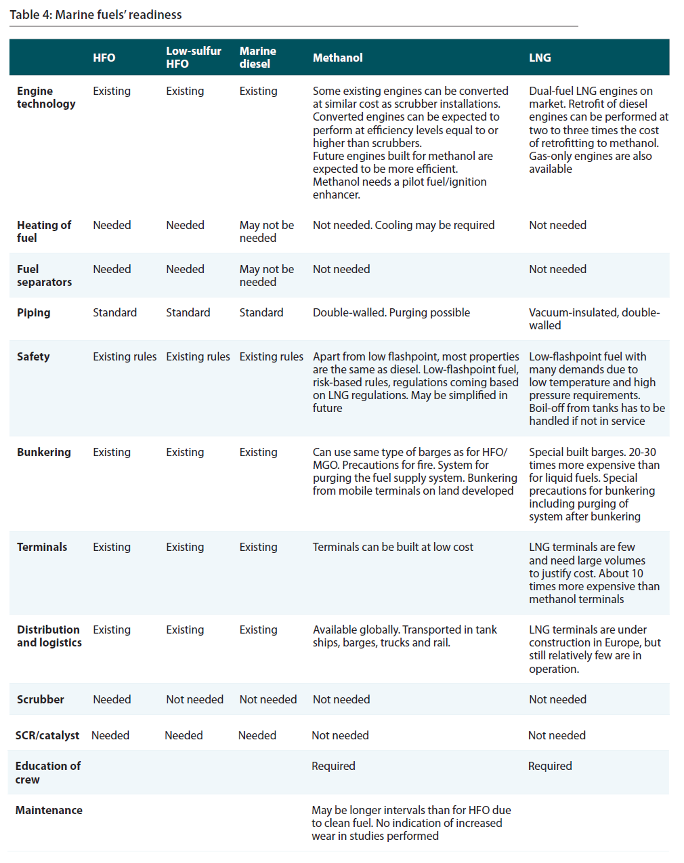
This blog is a comprehensive overview of using methanol as marine fuel in a (dual-fuel) combustion engine, based on reports made by IMO, G. Hagen, Marine Methanol and for the Methanol Institute. Key points for shipowners when considering methanol are:
Retrofit cost of a ship from diesel fuel to dual-fuel methanol/diesel fuel are estimated to be ranging between €250-350 up to €650/kW. Engine retrofit ranges between €250-350 up to €550/kW.
IMO IGF Code of safety for ships using gases or other low-flashpoint fuels is the governing standard for using methanol on board.
LNG engines are most suitable for retrofit, as the engines and other equipment are technically capable to handle methanol and much equipment including LNG tanks can possibly be re-used, including double-walled fuel distribution system and nitrogen purge.
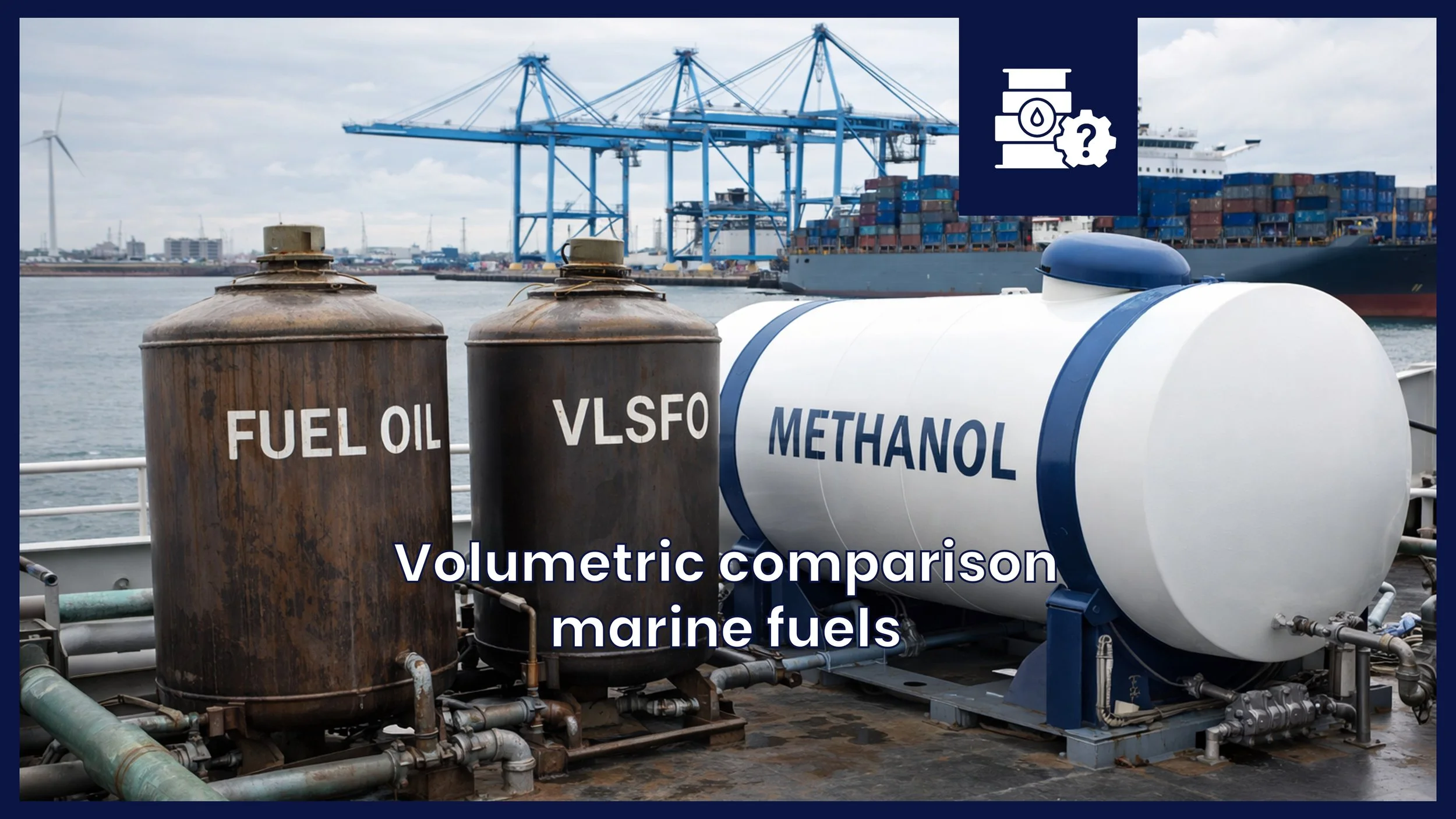
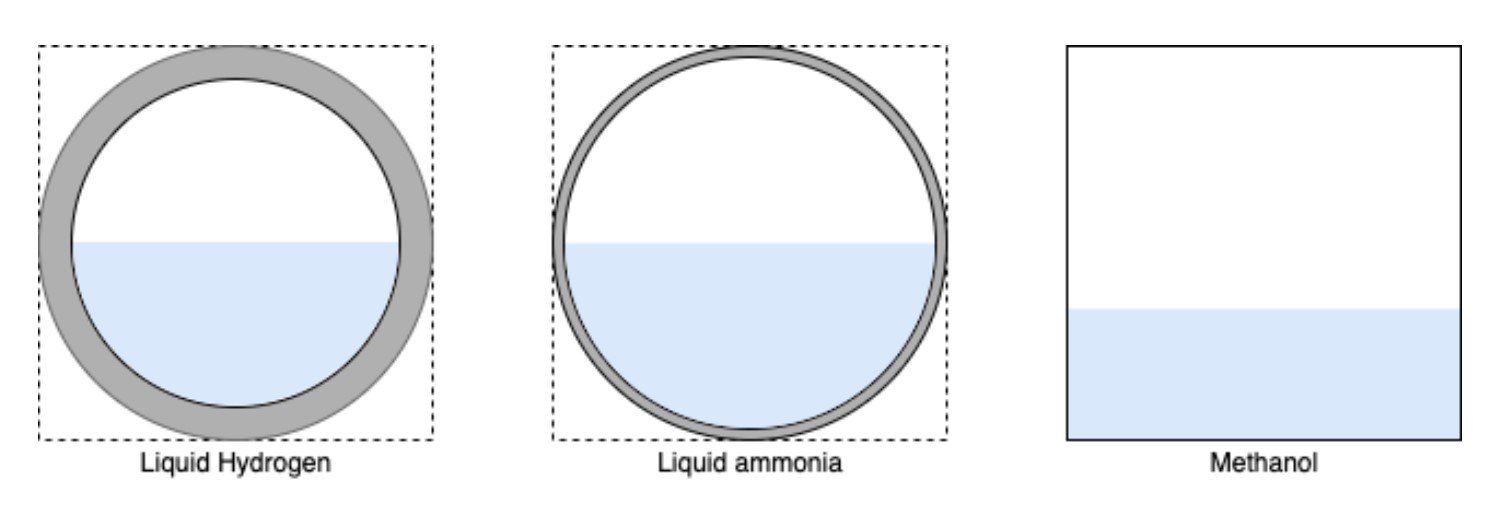
Methanol can be easily stored and pumped at ambient temperature. It can be stored in existing ballast tanks if vessel operations allow for this.
Use the Decarbonizer to quickly estimate retrofit costs for your vessel.
These figures highlight key features on methanol for marine use. They are elaborated upon in the below paragraphs.
All costs provided in this blogs are estimated, based on anecdotal evidence from research. The numbers are for feasibility study purposes. Contact your supplier for firm quotes.

Buy premium E-book
The e-book offers more information on methanol, includes all references
Also includes in-depth analyses on the cost impact of methanol on different ship types
Used by 1,000+ people each month - worldwide
Technical Overview
Methanol can be stored at ambient temperature and pressure.
All equipment needs to be double-walled and purged with nitrogen if needed.
Service and bunkering tanks can be made of stainless steel, possibly inside existing ballast tanks.
Methanol is an organic chemical and the simplest aliphatic alcohol, with the formula CH₃OH. It is a light, volatile, colourless, flammable liquid with a distinctive alcoholic odour similar to that of ethanol. Due to its very low viscosity compared to conventional HFO and diesel, special efforts are needed to ensure proper combustion and to prevent leaks in seals. The use of methanol on board ships is governed by the IMO IGF Code on low flashpoint fuels, which mandates many of the practical considerations that need to be taken when working with methanol.
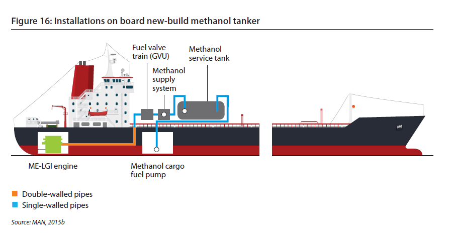
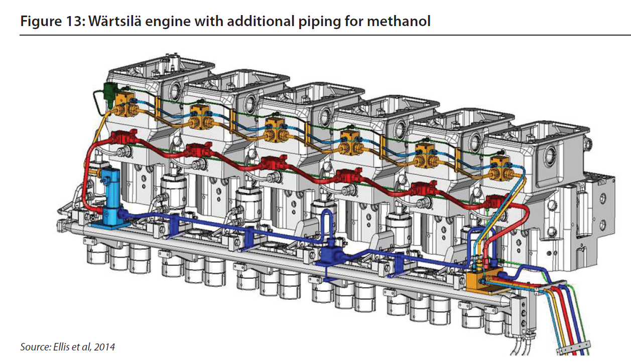
A key consideration is the fuel delivery system, which has to be safe for technicians carrying out maintenance or repairs. In practice this simply means to avoid direct contact with methanol. For this reason, methanol engines are equipped with double-walled fuel distribution systems, similar to LNG vessels. Methanol vapour is heavier than air and it will therefore move downwards, hence the placement of gas detectors and ventilation at lower elevations is essential. Additionally, the entire system including the engine itself is designed to be purged with nitrogen, ensuring that operators can work on the engine safely. In contrast to HFO, there is no need to heat the fuel; on the contrary, the fuel sometimes has to be cooled before injection.
Standards
IMO - IGF Code of safety for ships using gases or other low-flashpoint fuels
DNV - Pt.6 Ch2. Sec.8 Fuel Ready Ships
ABS - Guide for Methanol and Ethanol Fuelled Vessels
Lloyd’s - Rules for the Classification of Methanol Fuelled Ship
IRS - Guidelines on Methanol Fuelled Vessels
The IMO ’s International Code of Safety for Ships using Gases or other Low-flashpoint Fuels (IMO Res MSC.285(86) or IGF Code) is the international standard for ships using low-flashpoint fuel. The basic philosophy of this Code is to provide mandatory provisions for the arrangement, installation, control and monitoring of machinery, equipment and systems using low-flashpoint fuel to minimize the risk to the ship, its crew and the environment, having regard to the nature of the fuels involved.
According to the IGF Code the overall functional requirement is: the safety, reliability and dependability of the systems shall be equivalent to that achieved with new and comparable conventional oil-fuelled main and auxiliary machinery. This level of safety is found by conducting a risk assessment, hazard identification (HAZID) or failure mode, effect and criticality analysis (FMECA), of the fuel system. This is carried out in the design phase, to avoid risks and implement additional risk reducing measures in the design if the risk level is found to be high.
HAZID or FMEA elements
The safety assessment for Low Flashpoint Liquids (LFL) is divided into the following system elements:
-
Requirements regarding bunkering of methanol are according to DNV GL rules divided into the bunkering station and the fuel bunkering system individually:
Fuel bunkering station
The bunkering station shall be so located that sufficient natural ventilation is provided. The bunkering station shall be separated from other areas of the ship by gas tight bulkheads, except when located in the cargo area on tankers. Closed or semi-enclosed bunkering stations will be subject to special consideration with respect to requirements for mechanical ventilation.
Coamings shall be fitted below the bunkering connections.
Control of the bunkering shall be possible from a safe location in regard to bunkering operations. At this location the tank level shall be monitored. Overfill alarm and automatic shutdown is also to be indicated at this location.
Fuel bunkering system
A manually operated stop valve and a remote operated shutdown valve in series, or a combined manually operated and remote valve shall be fitted in every bunkering line close to the shore connecting point.
Bunkering pipes shall be self-draining.
Bunkering lines shall be arranged for inerting and gas freeing.
The connecting coupling for the transfer hose shall be of a type which automatically closes at disconnection (self-sealing type).
The configuration of the bunkering station and bunkering system is more comprehensive compared to conventional fuel oil, due to the nature of methanol as a fuel and its chemical and physical properties. Methanol is toxic and has a low flashpoint of only 12°C. Flashpoint is the minimum temperature at which a liquid gives off vapour in sufficient concentration to form an ignitable mixture with air. This methanol property in combination with a low needed ignition energy results in additional control barriers. Additional monitoring and control systems are therefore needed, such as overfill alarms, automatic shutdown, monitoring of ventilation and gas detection.
-
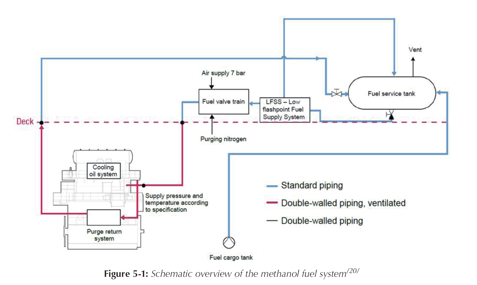
This part of the methanol fuel system consists of a fuel cargo tank in addition to a fuel service tank placed on deck. This is not the only possible solution regarding storage of methanol as fuel, but used as example study for illustration purposes.
Requirements regarding storage of methanol according to DNV GL rules/19/ are divided into location of fuel tanks, protection of fuel tanks, gas freeing, inerting, venting of fuel tanks and special concerns regarding tanks placed on weather decks.
Location of fuel tanks
Fuel shall not be stored within machinery spaces or accommodation spaces and the minimum horizontal distance between the fuel tank side and the ship’s shell shall be at least 760 mm.
The spaces forward of the collision bulkhead (forepeak) and aft of the aftermost bulkhead afterpeak) shall not be arranged as fuel tanks.
Two fuel service tanks for each type of fuel used on board necessary for propulsion and vital systems or equivalent arrangements shall be provided.
Each tank shall have a capacity sufficient for continuous rating of the propulsion plant and normal operating load at sea of the generator plant for a period of not less than 8 hours, if only methanol is used as fuel.
Protection of fuel tanks located inside the ship hull
Where not bounded by bottom shell plating or fuel pump room, the fuel tanks for Low Flashpoint Liquid (LFL) shall be surrounded by protective cofferdams.
The protective cofferdam surrounding the LFL fuel tank shall be arranged with vapour and liquid leakage detection and possibility for water filling upon detection of leakage. The water filling shall be through a system without permanent connections to water systems in non-hazardous areas. Emptying shall be done with a separate system. Bilge ejectors serving hazardous spaces shall not be permanently connected to the drive water system.
Gas freeing, inerting and venting of fuel tanks
Fuel tanks shall be provided with an arrangement for safe inert gas purging and gas freeing.
Fuel tanks without direct access from open deck shall have a sufficient number of ventilation inlets and outlets to ensure complete gas freeing, but no less than 2 inlets and 2 outlets per tank.
The tanks shall have an arrangement for pressure/vacuum relief or equivalent during voyage, bunkering and fuel transfer with closed tank hatch covers.
Individual pressure vacuum relief valves or an equivalent arrangement shall be fitted to each tank to limit the pressure or vacuum in the tank.
The venting system shall be designed with redundancy for the relief of full flow overpressure and vacuum. Pressure sensors fitted in each fuel tank, and connected to an alarm system, may be accepted in lieu of the redundancy requirement for pressure relief.
Pressure/vacuum safety valves shall be located on open deck and shall be of a type which allows the functioning of the valve to be easily checked.
Intake openings of pressure/vacuum relief valves shall be located at least 1.5 m above tank deck, and shall be protected against the sea.
The vent system shall be sized, allowing for flame screens, if fitted, to permit bunkering at a design rate without over-pressuring the tank. Specifically, under conditions in which a saturated fuel vapour is discharged through the venting system at the maximum anticipated bunkering rate, the pressure differential between the fuel tank vapour space and the atmosphere shall not exceed the design vapour pressure of the tank, or, for independent tanks, the maximum working pressure of the tank.
The venting system shall be connected to the highest point of each fuel tank and vent lines shall be self-draining under all normal operating conditions of list and trim.
The arrangement for gas freeing fuel tanks shall be such as to minimize the hazards due to the dispersal of flammable vapours in the atmosphere and to flammable vapour mixtures in a fuel tank. The ventilating system used for gas freeing of fuel tanks shall be used exclusively for ventilating purposes.
Fuel tanks on weather deck
LFL fuel tanks on open deck shall be protected against mechanical damage.
LFL deck tanks on open deck shall be surrounded by coamings.
Special considerations shall be taken to minimize any fire hazards adjacent to the fuel tanks on weather deck. Protection of the LFL fuel tanks from possible fires on board may be subject to a fire safety assessment in each particular case.
The configuration of the methanol fuel storage tank is more complex compared to conventional fuel oil, due to the nature and properties of methanol as a fuel. Additional monitoring and control systems are needed, such as overfill alarms and shutdown, monitoring of ventilation liquid and gas detection.
Methanol vapour is heavier than air and it will therefore move downwards, hence the placement of gas detectors and ventilation at lower elevations is essential.
Fire detection systems in spaces adjacent to fuel storage and firefighting systems are also needed. Especially fire detection systems are important, due to the fact that a methanol-based fire burns invisibly, unlike gasoline, which burns with a visible flame. Fire detection with infrared cameras is therefore a possible solution to this problem in combination with water spray firefighting systems.
-
Requirements regarding handling and processing of methanol towards the main engine according to DNV GL rules are divided into general issues, protection of fuel transfer system, valves, fuel pumps and temperature control.
General
The fuel system shall be entirely separate from all other piping systems on board.
The piping shall be located no less than 760 mm from the ship side.
For vessels using LFL as their only fuel, the fuel supply system shall be arranged with redundancy and segregation all the way from the fuel tank to the consumer, so that a leakage in the fuel supply system with following necessary safety actions does not lead to loss of propulsion, power generation or other main functions.
All piping containing LFL shall be arranged for gas freeing and inerting.
The design pressure p is the maximum working pressure to which the system may be subjected. The design pressure for fuel piping is as a minimum to be taken as 10 bar. Due consideration shall be given to possible liquid hammer in connection with the closing of valves.
Drip trays shall be installed below all possible leakage points in the fuel system.
Protection of fuel transfer system
Fuel piping shall be protected against mechanical damage.
All piping containing LFL that passes through enclosed spaces in the ship shall be enclosed in a pipe that is gas tight and water tight towards the surrounding spaces with the LFL contained in the inner pipe.
Fuel piping shall normally not be led through accommodation spaces, service spaces or control stations. In cases where fuel piping must be led through accommodation spaces, the double walled fuel piping shall be led through a dedicated duct. The duct shall be of substantial construction and be gas tight and water tight.
The annular space in the double walled fuel pipe shall be ventilated to open air and be equipped with vapour and liquid leakage detection. Inerting of the annular space in the double walled fuel piping may be accepted as an alternative in low pressure fuel systems. The inerted annular space shall be pressurized with inert gas at a pressure greater than the fuel pressure. Suitable alarms shall be provided to indicate a loss of inert gas pressure between the pipes.
Valves
LFL storage tank inlets and outlets shall be provided with remotely operated shut-off valves located as close to the tank as possible. The tank valve shall automatically cut off the LFL supply.
Valves that are required to be operated during normal operation and which are not accessible shall be remotely operated. Normal operation in this context is when fuel is supplied to consumers and during bunkering operations.
The main supply lines for fuel to each engine room shall be equipped with automatically operated master LFL fuel valves. The shut-off valve shall be situated outside the engine room. The master LFL fuel valve shall automatically cut off the LFL supply to the engine room.
The LFL fuel supply to each consumer shall be provided with a remote shut-off valve.
There shall be one manual shutdown valve in the LFL supply line to each engine to assure safe isolation during maintenance on the engine.
All automatic and remotely operated valves are to be provided with indications for open and closed valve positions at the location where the valves are remotely operated.
Fuel pumps
Any pump room shall be located outside the engine room, be gas tight and water tight to surrounding enclosed spaces and vented to open air.
Hydraulically powered pumps that are submerged in fuel tanks (e.g. deep well pumps) shall be arranged with double barriers preventing the hydraulic system serving the pumps from being directly exposed to the fuel.
The double barrier shall be arranged for detection and drainage of possible fuel leakages.
LFL pump rooms shall be provided with a dedicated bilge system, operable from outside the pump room. Bilge ejectors serving hazardous spaces shall not be permanently connected to the drive water system. The bilge system may have possibilities for discharge to a suitable cargo tank, slop tank or similar, however, taking into account hazards related to incompatibility.
Temperature control
The temperature control system shall be arranged as a secondary system independent of other ship’s services and shall be provided with valves to isolate the system for each supply line or tank.
For any temperature control system, means shall be provided to ensure that, when in any other but the empty condition, a higher pressure is maintained within the system than the maximum pressure head exerted by the fuel tank content on the system.
The temperature control circuit expansion tank shall be fitted with a gas detector and low level alarm and be vented to open air.
-
Requirements regarding combustion of methanol in the main engine according to DNV GL rules is divided into general issues, functional requirements for dual fuel engines and functional requirements for LFL-only engines.
General, applies to both LFL fuel only and dual fuel engines
Measures shall be taken to ensure effective sealing of injection or admission equipment that could potentially leak fuel into the engine room.
Measures shall be taken to ensure that LFL fuel injection pumps and injection devices are efficiently lubricated.
The starting sequence must be such that LFL fuel is not injected or admitted to the cylinders until ignition is activated and the engine has reached a minimum rotational speed. In this respect pilot fuel is needed.
If ignition has not been detected by the engine monitoring system within expected time after activation of fuel admission or injection valve, the LFL fuel supply shall be automatically shut-off and the starting sequence terminated.
Functional requirements for dual fuel engines
LFL dual fuel engines shall be able to start, normal stop and stable low power operation safely. In case of shut-off of the LFL fuel supply, the engine shall be capable of continuous operation on oil fuel only.
Changeover to and from LFL fuel operation is only to be possible at a power level where it can be done with acceptable reliability as demonstrated through testing. On completion of preparations for changeover to LFL operation including checks of all essential conditions for changeover, the changeover process itself shall be automatic.
On normal shutdown as well as emergency shutdown, LFL fuel supply shall be shut-off not later than simultaneously switching to oil fuel mode.
Firing of the LFL-air mixture in the cylinders shall be initiated by sufficient energy to ensure effective ignition with corresponding combustion of the LFL-air mixture. It shall not be possible to shut-off the ignition source without first or simultaneously closing the LFL fuel supply to each cylinder or to the complete engine.
Functional requirements LFL-only engines
One single failure in the LFL fuel supply system shall not lead to total loss of fuel supply.
-
All piping containing LFL shall be arranged for gas freeing and inerting.
There shall be one manual shutdown valve in the LFL supply line to each engine to assure safe isolation during maintenance on the engine.
These requirements are functional and therefore up for interpretation from the designer and maker of the fuel system. Several solutions exist, but the main common denominator is that the methanol fuel system needs to be drained, purged and gas freed, throughout the entire system. This is also applicable for the residues in the main engine. Methanol is finally collected, back into the service tank, or to an additional residue tank.
The nitrogen installation plays a central role in the total cycle and the requirements to the nitrogen installation is presented in the following:
All tanks containing LFL shall be inerted.
To prevent the return of fuel vapour to any gas safe spaces, the inert gas supply line shall be fitted with two shut-off valves in series with a venting valve in between (double block and bleed valves). In addition a closable non-return valve shall be installed between the double block and bleed arrangement and the fuel tank. These valves shall be located outside non-hazardous spaces and must function under all normal conditions of trim, list and motion of the ship. The following conditions apply:
Where the connections to the fuel tanks or to the fuel piping are non-permanent, two non-return valves may substitute the non-return devices required above.
Low-pressure alarm shall be provided in the nitrogen supply line on the fuel tank side of any double block and bleed valves and pressure reduction units. If pressure/vacuum alarms are fitted in each fuel tank as means to comply with redundant venting requirements, a separate low-pressure alarm is not required.
A high oxygen content alarm shall be provided in the engine control room. The alarm is to be activated when the oxygen content in the inert gas supply exceeds 5%.
Where a nitrogen generator or nitrogen storage facilities are installed in a separate compartment, outside of the engine room, the separate compartment shall be fitted with an independent mechanical extraction ventilation system, providing 6 air changes per hour. A low oxygen alarm shall be fitted. Such separate compartments shall be treated as one of other machinery spaces, with respect to fire protection.
To handle methanol after the main engine is especially related to dual fuel engines and in the case of a fuel switchover. It is also important to the above mentioned requirement, in the case of maintenance of the engine. Hence there are a number of scenarios where the fuel piping will have to be emptied for methanol, due to the low flashpoint and the toxicity of the fuel.
According to MAN Diesel & Turbo for their engine, fuel piping to the engine and in the engine room is arranged so that the liquid fuel can be purged and thereby returned to the fuel service tank. After the methanol fuel has been returned to the service tank, full purging and inerting are conducted for the double walled piping system. All purging and inerting is distributed, for every subsystem, by the nitrogen installation.
Engine retrofit requirements
Methanol needs a pilot fuel or other ignition enhancer to operate. Battery packs for power ramp-up might be required.
Methanol engines are equipped with double-walled fuel distribution systems capable to be purged with nitrogen.
(Dual-fuel) LNG engines are most suited for methanol as LNG engines and equipment also adhere to the IGF code.
The conventional fuel system can be kept operable as a spare system.
Combustion
The use of methanol presents lubrication requirements that are substantially different than those of conventional fuels. Using methanol as a fuel generally promotes a cleaner lubricant environment, but induces significantly greater engine wear compared to fuel oil. This wear may affect engine operation and durability.
For engine retrofitting, fuel injection is to be modified to achieve higher injection pressure for igniting methanol. Consequently most engines running on methanol will still require a pilot fuel or other ignition enhancer to operate. The low cetane number is a property that methanol shares with LNG and the engine will need a cetane enhancer in order to ignite. In the dual-fuel solution, a small amount of diesel oil is used as a pilot fuel.
A difference from the gas dual-fuel engine is that the gas compressor used for natural gas is replaced by high-pressure methanol pumps to increase fuel pressure. Methanol injection is performed via a common rail system. All piping for methanol is designed as double-walled installations. The methanol in the high-pressure piping system can be purged free by nitrogen gas to allow service without operators coming into contact with the methanol.
Efficiency
Wärtsilä tests indicate that the fuel efficiency is the same or better when running on methanol. Stena’s experience indicates that they have better fuel efficiency in the order of 1-2% when running on methanol, although they have not performed tests to document the change in efficiency. It is therefore assumed that the energy efficiency in marine engines remains unchanged when running on methanol. There is increased lubrication oil consumption when running on methanol, but this was considered negligible.
For heavy-duty operations and to accomodate high power ramp-up requirements, battery packs might be required as methanol engines tend have lower response time. This requirement is similar to when dual-fuel LNG engines were made and engine manufacturers are continuously improving methanol combustion engines to increase power ramp up.
Retrofit time
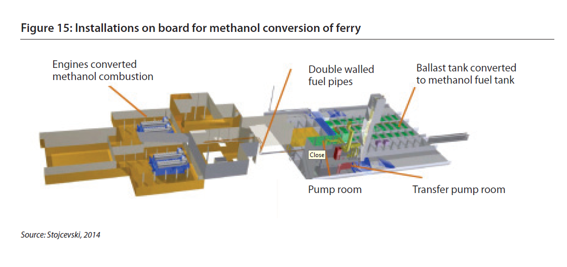
The time at yard for methanol conversion of one engine of the Stena Germanica (24 MW ro-ro pax) was two weeks. After installation of the fuel tanks and fuel system, additional engines were converted during operation.
Equipment retrofit requirements and CAPEX costs
All costs provided in this blogs are estimated, based on anecdotal evidence from research from the references stated below. The numbers are for feasibility study purposes. Contact your supplier for quotes.
-
Methanol is liquid at ambient temperatures, making it easier to store compared to LNG or other hydrogen-carriers. There are no limitations regarding the storage capacity of methanol tanks since the fuel is a liquid at ambient temperature. Methanol does has corrosive properties which need to be mitigated by storing it in stainless- or carbon steel tanks. The low flashpoint requires extra venting- and gas detection systems to prevent gas build up in the tanks and on-board, equivalent to using LNG. According to G. Hagen, the costs for storing methanol are in the order of €0.14 per kWh for retrofits.
However, DNV-GL rules for classification restrict the locations of the cargo and service tanks. The service tank must be positioned on deck and have a venting system installed so direct venting of fuel gasses can be executed in case of emergency’s. The cargo tank can be installed below deck but must be positioned at least 760 mm from the hull for inspection access.
The installation cost of a small bunkering unit for methanol has been estimated at around € 400,000 (Stefenson, 2015). This order of magnitude in costs corresponds with the FCBI newbuild example for storage tanks. For bunker large vessels, an existing barge can be converted into a bunker vessel for methanol at a cost of approximately € 1.5 million. For a 20,000 m3 methanol tank and the installations for loading the tank from a tank vessel and unloading it to a bunker vessel, the cost is approximately €5 million (Stefenson 2015).
-
All piping for the complete fuel supply system has to be double walled and entirely separated from all other piping systems. All piping below deck must not only be double walled but also ventilated. The entire system must be purged with nitrogen for repair and maintenance purposes. According to G. Hagen, the costs for handling methanol and retrofitting the piping system are in the order of €57 per kW. FCBI estimates a total cost of €100 per kW for newbuild fuel handling and piping.
-
FCBI estimates newbuild engine costs to be in the order of €112.5 per kW. This correlates nicely with their statement that conversion cost of a second retrofit project are estimated at 30% to 40% compared to first conversion. G. Hagen estimates the retrofit cost of an engine from dual-fuel LNG/diesel to methanol/hydrogen combustion to be approximately €550/kW. It should be noted that this conversion is more technically demanding compared to ‘conventional’ dual fuel.
It should be noted that IMO also states that is easier to use a dual fuel engine than to custom retrofit an engine, hence the price difference between newbuild and retrofit.
-
Exhaust valves are to be checked for their ability to resist wear and tear from exhaust gas with fewer lubricating particulates compared to heavy fuel oil. If needed, they need to be replaced.
CAPEX Examples
-
Purchase E-Book and receive all information!
-
Purchase E-Book and receive all information!
-
Purchase E-Book and receive all information!
-
Purchase E-Book and receive all information!
OPEX Costs
-
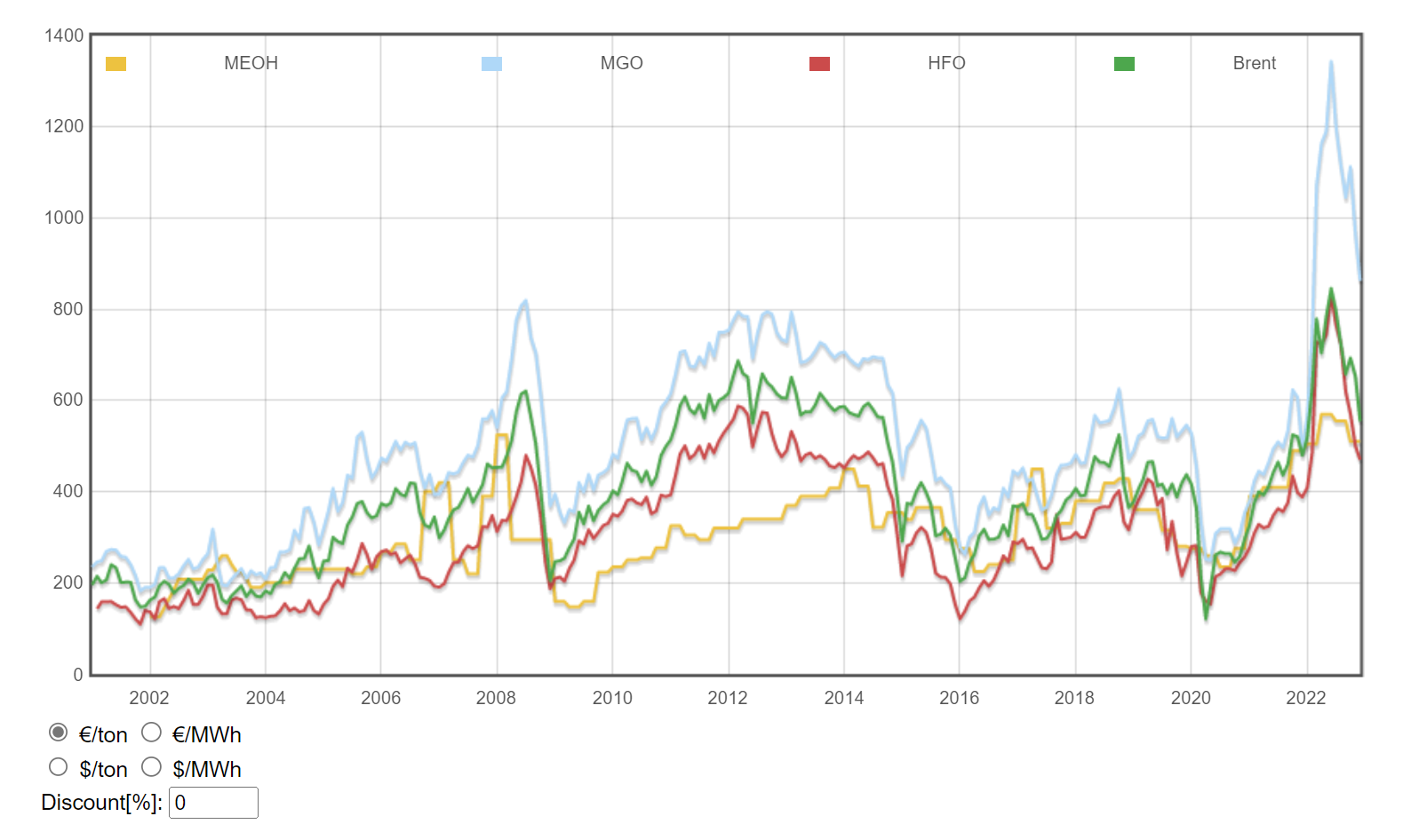
Marine Methanol has a historical overview of marine fuel prices. This graph shows methanol costs have varied between €180 and €580 per mT in the past 10 years, with lower price fluctuations of methanol compared to conventional fuel (in particular MGO). It should be noted that these prices are for the chemical industry and to not correlate directly to use of methanol on board. Bunkering of fuel is not reflected properly in this pricing.
FCBI estimates that a large ferry conversion to methanol, with diesel fuel consumption of a < 10,000 m3/year, would achieve payback in three to five years with methanol prices $ or € 100-200 lower per ton of MGO equivalent.

Availability
Availability of methanol worldwide for chemical industry is excellent.
Bunkering for smaller vessels via land-based logistics, i.e. trucks.
Bunkering for larger vessels virtually non-existent.
Less than 1% of worldwide methanol is ‘green’ or e-methanol (to be verified).
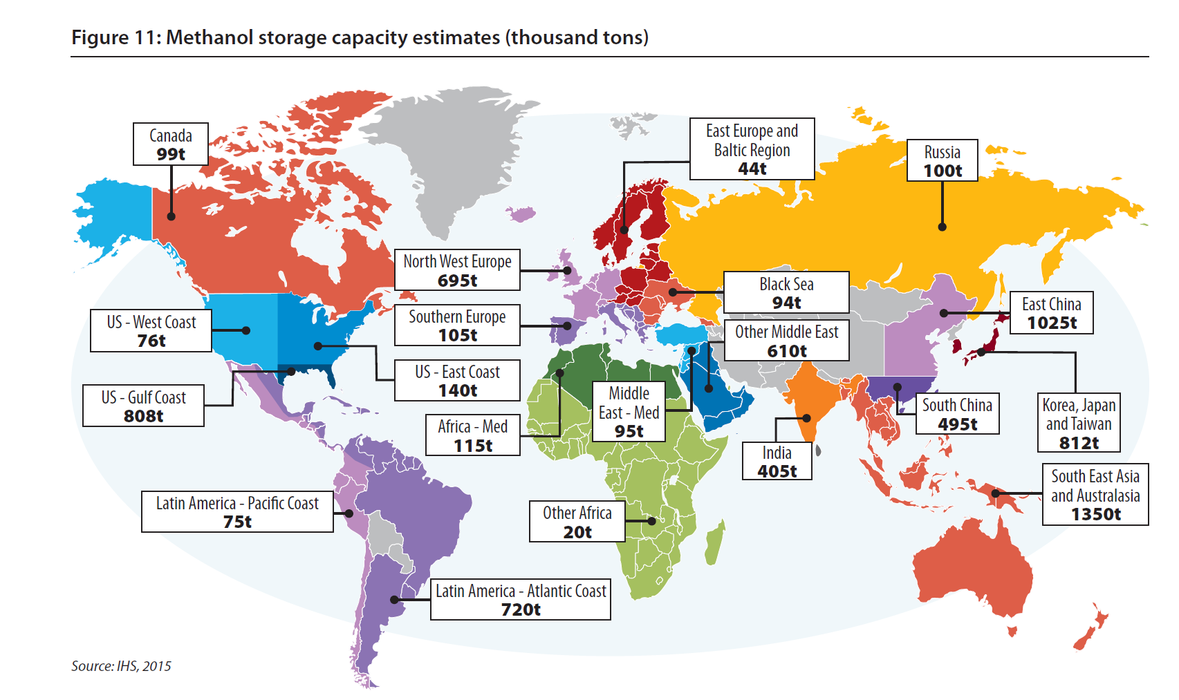
Global annual methanol production capacity currently exceeds 100 million tons and is mainly used in the chemical industry. Fuel accounts for ‘only’ nine million tons, mostly used as blend in gasoline. The global demand has grown in the last few years. In 2014, demand was estimated at around 65–70 million tons, out of which at least 40 million tons were used in China (IHS, 2015). Methanol is available in all major shipping hubs globally, but the last mile to ship is currently not commoditized. In practice, this means supply chains have to be self-made in the coming years, especially for large vessels that cannot be serviced with a truck.
Infrastructure
The infrastructure for methanol available today is based on the worldwide distribution of methanol to the chemical industry. This ensures widespread availability, although there may be a need for additional terminals for ship fuel. Within the SECAs, there are numerous terminals that serve the chemical industry. For some ports in Europe, methanol is one of the leading chemicals in terms of volume handled. The distribution of methanol from the hubs is performed by 1,200-ton barges, rail, or tank trucks.
Bunkering
Currently, bunkering of methanol fueled ships is performed by truck (Stefenson, 2014). The trucks deliver the methanol to a bunkering facility with pumps built in containers on the quay next to the ferry. This is a solution that is flexible and easy to build. The technology and safety precautions build on long experience from methanol deliveries for other applications. The first of these fueling facilities has been in service since April 2015. Where there are several ships using methanol that bunker in a port, existing bunker ships may be converted.
Emissions
IMO
CO2 and NOx emission factors for methanol vary significantly, ranging from 15% - 80%+ reduction in the case of CO2. SOx and CH4 emissions are reduced by 100%.
As with regular fossil fuels, CO2 emissions from combustion of methanol are based on the carbon content per MJ fuel. The carbon content can vary slightly according to the purity of fuel; however, purity of the product is well controlled in the production process. IMO estimates that methanol combustion emits 69 grams CO2 per MJ methanol combusted.

FCBI Energy / Wärtsilä
Wärtsilä has tested NOx emissions from methanol against those from HFO in two engine models: pre-tests on the Wärtsilä Vasa 32, and full tests on the Sulzer Z40S-MD. Their results show that NOx emissions were approximately 40% of emissions from HFO from the same engines at similar load. However, the NOx emissions were not as low as Tier III levels. The report therefore assumes that NOx emissions during combustion are reduced by approximately 60% when running on methanol compared to HFO. Next to NOx emissions, the following results from laboratory tests with a Wärtsilä methanol MGO dual fuel engine are shared (Stojcevski, 2014):
NOx 3.5 g/kWh (Low Tier II, no major conversion)
CO (< 1 g/kWh)
THC (< 1 g/kWh)
PM only from MGO pilot (FSN ~ 0,1)
SOx only from MGO pilot (99% reduction)
Formaldehyde emissions (~ below TA-luft)
No formic acid detected in exhaust gases
No reduction in output and load response unchanged, full fuel redundancy
Higher efficiency (tests show lower fuel consumption in methanol mode)
Man
MAN Diesel has performed tests with a methanol in marine diesels resulting in a 30% reduction in NOx emissions compared to diesel. Although the results of tests from Wärtsilä and MAN differ, both indicate a significant decrease in NOx reduction when using methanol. Additionally, NOx emissions are dependent on combustion condition, meaning that any parameter indicating NOx emissions per MJ fuel will contain some uncertainty. This is equivalent to regular fossil fuel engines.
HSE - Working with Methanol
Avoid direct contact
And explosions
Avoiding explosions is generally a good advice for any circumstance, methanol is special however. Due to the low flash point of methanol, explosion hazard is the most important factor to consider in the design of the fuel supply line. In addition, methanol has corrosive properties which need to be mitigated by storing it in stainless- or carbon steel tanks. The low flashpoint also imposes other restrictions on the tanks. Similar to LNG, these are mostly focused on the extra venting- and gas detection systems to prevent gas build up in the tanks. All piping should be double walled and the complete fuel supply system has to be entirely separate from all other piping systems. All piping below deck mustbe double-walled and ventilated.
Toxicity
Methanol is toxic if swallowed, comes in contact with skin or if vapour is inhaled. If methanol is ingested in relatively large quantities it will be metabolized to formic acid or formate salts, which is poisonous to the central nervous system and may cause blindness, coma and death. The high toxicity level implies that if as little as 10 mL of pure methanol is ingested, it can break down into formic acid, which can cause permanent blindness. 30 mL is potentially fatal, although the median lethal dose is about 100 mL. The toxic effects take hours to start, and effective antidotes can often prevent permanent damage. Methanol vapour is heavier than air and it will therefore move downwards, hence the placement of gas detectors and ventilation at lower elevations is essential.
Low flashpoint
Methanol is toxic and has a low flashpoint of only 12°C. Flashpoint is the minimum temperature at which a liquid gives off vapour in sufficient concentration to form an ignitable mixture with air. This methanol property in combination with a low needed ignition energy results in additional control barriers. Additional monitoring and control systems are therefore needed, such as overfill alarms, automatic shutdown, monitoring of ventilation and gas detection.
Ship type considerations
Ship specific requirements according to the DNV GL rules are divided into the following ship types: Working ships (e.g. offshore supply vessel), Cargo ships (e.g. chemical tanker) and Passenger vessels (e.g. cruise ship).
-
For this group, additional requirements apply regarding general aspects.
General
LFL fuel tanks on deck are not accepted on offshore supply vessels.
The aft- and forepeak in offshore supply vessels cannot be used as cofferdam space for a LFL fuel tank.
-
For this group, additional requirements apply regarding arrangement, fire safety and segregation of cargo- and fuel system.
Arrangement
A dedicated LFL fuel service tank shall be provided. The piping system serving this tank shall be separated from cargo handling piping systems, except for the fuel transfer pipes from tanks for fuel storage.
Fire safety
Measures shall be implemented to reduce the consequences of fire and explosions in cargo tanks and in the cargo area for the dedicated LFL fuel service tanks and LFL fuel supply systems.
Inerting of cargo tanks during cargo tank cleaning operations and inert gas purging prior to gas freeing would be considered an acceptable measure to reduce the consequence of in-tank explosion. Such inerting should be performed for all cargo tanks and regardless of size of ship.
LFL fuel tanks and associated tank connection spaces (if fitted) on weather deck shall be protected by a water spray system for cooling and fire prevention and to cover exposed parts of the tank located on open deck.
This system comes in addition to the deck foam firefighting system required for chemical tankers.
For the purpose of isolating damaged sections, manual stop valves shall be fitted or the system may be divided into two sections with control valves located in a safe and readily accessible position not likely to be cut-off in case of fire.
The system shall be served by a separate water spray pump with capacity sufficient to deliver the required amount of water.
A connection to the ship’s fire main through a stop valve shall be provided.
Segregation of cargo- and fuel system
Measures shall be provided to prevent inadvertent transfer of incompatible or contaminating cargo to the fuel system, after the fuel storage tanks have been loaded.
If cargo tanks located within the cargo area are used as LFL fuel storage tanks, these cargo tanks shall be dedicated as LFL fuel tanks when the ship is operating on LFL fuel.
Any cargo liquid line for dedicated LFL fuel storage tanks shall be separated from liquid cargo piping serving other cargo tanks, including common liquid cargo piping.
Cross-connections to cargo liquid piping serving common systems or other tanks may be accepted provided the connections are arranged with spool pieces, typically swing bends. The arrangement of spool pieces shall be such that even if a spool piece is unintentionally left in place, inadvertent transfer of incompatible or contaminating cargo from or to the dedicated LFL fuel storage tank is not possible. The piping and manifold serving the dedicated LFL fuel storage tanks shall be specially colour coded.
The cargo tank venting system for the dedicated LFL fuel tanks shall be separated from venting systems from other cargo tanks when operating on LFL fuel.
Other cargo handling systems serving other cargo tanks such as tank washing, inert gas and vapour return shall be separated when used as LFL fuel storage tanks. Inert gas systems may be accepted connected to a common system when used as LFL fuel storage tanks, provided the system is under continuous pressure.
LFL fuel tank location shall take into account compatibility with other cargoes. When carrying LFL fuel in the storage tanks, these tanks cannot be located adjacent to cargo tanks intended for cargoes that are not compatible with the LFL fuel.
-
For this group, additional requirements apply regarding general aspects.
General
Areas classified as hazardous zone shall be inaccessible for passengers at all times.
The aft- and forepeak in passenger vessels cannot be used as cofferdam space for a LFL fuel tank.
The main differences between these ship types are found for chemical tankers and are mainly considering additional fire safety and additional requirements to avoid contamination of the fuel from the cargo.
References
Save time and purchase e-book for hyperlinks
IMO - Methanol as marine fuel
IMO - IGF Code of safety for ships using gases or other low-flashpoint fuels
FCBI Energy - Methanol as a marine fuel report for the Methanol Institute
G. Hagen - Hydrogen powered propulsion for an offshore crane vessel
Marine Methanol - Fuel price comparison
DNV - Pt.6 Ch2. Sec.8 Fuel Ready Ships
ABS - Guide for Methanol and Ethanol Fueled Vessels